Installation and operation manual
7
FXLQ20~63P7VEB
VRV System air conditioners
4PW53089-1B
Wiring installation
Remove the control box cover and connect the wiring.
If wiring from the piping side, wire as shown in the figure below.
WIRING EXAMPLES
Fit the power supply wiring of each unit with a switch and fuse as
shown in figure 1.
Complete system example (3 systems)
When using 1 remote controller for 1 indoor unit. (Normal operation)
(See figure 2)
For group control or use with 2 remote controllers (See figure 4)
When including BS unit (See figure 3)
PRECAUTIONS
■ A single switch can be used to supply power to units on the
same system. However, branch switches and branch circuit
breakers must be selected carefully.
■ For a group control remote controller, choose the remote
controller that suits the indoor unit which has the most functions.
■ Do not ground the equipment on gas pipes, water pipes,
lightning rods or crossground with telephones. Improper
grounding could result in electric shock.
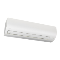
1 Control box
2 Power supply wiring (field supply)
3 Remote controller wiring (field supply)
4 Transmission wiring (field supply)
5 Clamp fastener
6 Clamp (accessory part)
7 Cut off excess after fastening
NOTE
For control box wiring, also refer to the "Electric Wiring
Diagram" label on the control box cover.
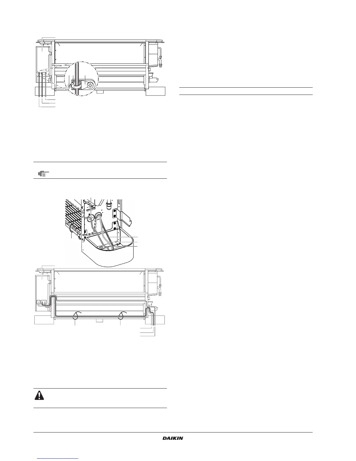
1 Pass through hole of opposite frame panel in same manner
2 Remote controller wiring
3 Transmission wiring
4 Power supply wiring and ground wiring
5 Control box
6 Fasten with clamp (accessory part)
Do not switch the remote controller wiring, transmission
wiring and power supply wiring when connecting the wires
to the terminal blocks.
1
4
3
2
76 5
3x
3x
4
2
3
4
3
2
6
6
6
1
5
1 Power supply 6 BS unit (only for heat
recovery system)
2 Main switch
3 Outdoor unit 7 Power supply wiring
4 Indoor unit 8 Transmission wiring
5 Remote controller 9 Switch
10 Fuse
1 Outdoor unit
2 Indoor unit
3 Remote controller (optional accessories)
4 Most downstream indoor unit
5 For use with 2 remote controllers
6 BS unit
 Loading...