FXLQ20~63P7VEB
VRV System air conditioners
4PW53089-1B
Installation and operation manual
6
- When connecting wires of the same dimension, connect
them according to the figure.
Use the specified electric wire. Connect the wire securely to the
terminal. Lock the wire down without applying excessive force to
the terminal. Use torques according to the table below.
- When attaching the control box lid, make sure not to pinch
any wires.
- After all wiring connections are done, fill in any gaps in the
casing wiring holes with putty or insulation material (field
supply) thus to prevent small animals or dirt from entering the
unit from outside and causing short circuits in the control box.
2 Keep total current of crossover wiring between indoor units less
than 12 A. Branch the line outside the terminal board of the unit
in accordance with electrical equipment standards, when using
two power wiring greater than 2 mm
2
(Ø1.6).
The branch must be sheathed in order to provide an equal or
greater degree of insulation as power supply wiring itself.
3 Do not connect wires of different dimensions to the same
grounding terminal. Looseness in the connection may
deteriorate the protection.
4 Remote controller cords and wires connecting the units should
be located at least 50 mm away from power supply wiring. Not
following this guideline may result in malfunction due to
electrical noise.
5 For the remote controller wiring, refer to the "Installation manual
of the remote controller" supplied with the remote controller.
6 Use only specified wires and tightly connect wires to the
terminals. Be careful that wires do not place external stress on
the terminals. Keep wiring in neat order so that they do not
obstruct other equipment such as popping open the control box
cover. Make sure the cover closes tight. Incomplete connections
could result in overheating, and in the worse case, electric shock
or fire.
7 Fasten wiring with clamps (accessory part).
Electrical characteristics
Specifications for field supplied fuses and wire
Allowable length of transmission wiring between indoor and outdoor units,
and between the indoor unit and the remote controller is as follows:
1. Outdoor unit - indoor unit: max. 1000 m
(total wiring length: 2000 m)
2. Indoor unit - remote controller: max 500 m
HOW TO INSTALL THE REMOTE CONTROLLER
AND WIRING INSIDE THE UNIT
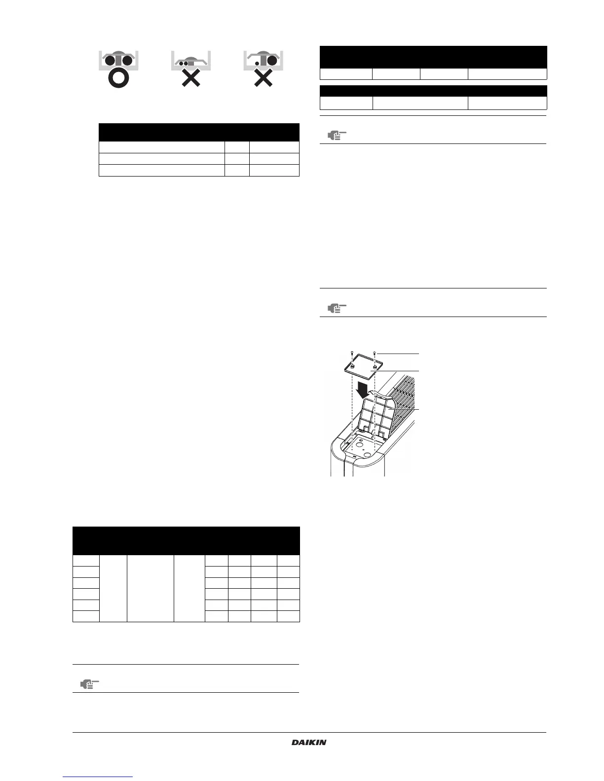
Remote controller installation
If mounting a remote controller on the unit, mount the remote
controller (optional accessory) as shown in the figure.
Open the left side lid of the control panel and mount the lower case of
the remote controller.
Terminal Size
Tightening
torque (N•m)
Te rminal block for remote controller M3.5 0.79~0.97
Power supply terminal block M4 1.18~1.44
Ground terminal M4 1.44~1.94
Model Hz Volts
Voltage
range
Power
supply
Fan motor
MCA MFA kW FLA
20
50/60 220-240/220 ±10%
0.3 15 0.015 0.2
25 0.3 15 0.015 0.2
32 0.6 15 0.025 0.5
40 0.6 15 0.025 0.5
50 0.6 15 0.035 0.5
63 0.6 15 0.035 0.5
MCA: Minimum Circuit Amps (A)
MFA: Maximum Fuse Amps (A)
FLA: Full Load Amps (A)
NOTE
For details, refer to "Electrical data" in the technical
data book.
Power supply wiring
Model Field fuses Wire Size
20~63 16 A H05VV-U3G Local codes
Model Wire Size
20~63
Sheathed wire (2)
0.75-1.25 mm
2
NOTE
For details, refer to "Wiring examples" on page 7.
NOTE
Refer to the installation manual of the remote controller
for instructions on fastening and wiring work.
1 Installation screw
2 Lower case of remote
controller
3 Lid of control panel
1
2
3
 Loading...