1.3 Disassembly Guidelines
NOTICE
To make the disassembly/reassembly process easier, use
these general guidelines:
1. Follow the disassembly instructions for each
component.
2. Place the component together with the removed
fasteners.
3. Replace old component with the new component
provided in the kit.
4. If any fasteners are stripped or lost, replace with
similar fastener from the kit.
5. Follow the assembly instructions to replace and
secure each component.
1.3.1 General Torque Tightening Values
Use a torque wrench to ensure that correct torque is applied.
Incorrect torque can cause electrical connection problems. For
fastening hardware described in this instruction, use the values
listed in Table 1.5 to Table 1.7 except where noted in the
procedures.
Shaft
size
Tor x/hex
drives size
Class A
Nm (in-lb)
Class B
Nm (in-lb)
M4 T20/7 mm 1.2 (10) 0.8 (7)
M5 T25/8 mm 2.3 (20) 1.2 (10)
M6 T30/10 mm 3.9 (35) 2.3 (20)
M8 T40/13 mm 9.6 (85) 3.9 (35)
M10 T50/17 mm 19.1 (169) 9.6 (85)
M12 –/18 mm or
19 mm
37.9 (335) –
Table 1.5 Torque Values Standard Thread
Shaft
size
Torx drives
size
Class A
Nm (in-lb)
Class B
Nm (in-lb)
M4.8 T25 5.7 (50) 3.1 (27)
M5 T25 1.7 (15) 1.7 (15)
Table 1.6 Torque Values for Thread Cutting into Metal
Shaft
size
Tor x drives
size
Class A
Nm (in-lb)
Class B
Nm (in-lb)
M4 T20 2.8 (24) 2.8 (24)
M5 T25 5.1 (45) 4.0 (35)
Table 1.7 Torque Values for Thread Forming into Plastic
Class A: Clamping metal
Class B: Clamping PCA or plastic
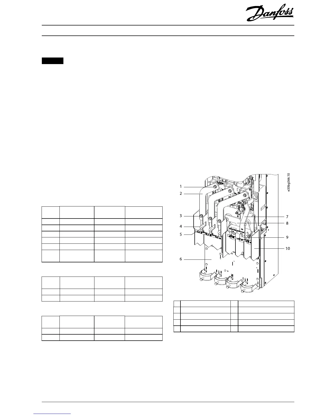
1.3.2 Removing AC Input Busbars
To remove the AC input busbars, use the following steps. The
AC input busbars can look
dierent
when the drive includes
extra input options, such as RFI lter or mains fuses.
Illustration 1.2 shows the AC input busbars congured to
include mains fuses.
1. Remove the air bae by removing 4 screws (T25)
and 2 nuts (13 mm).
2. Disconnect the customer input power wiring.
3. The next step
diers
based on the input options
present in the drive. Select the appropriate procedure
for the drive:
•
No options
•
Mains fuses only
•
RFI lter only
•
Mains fuses and RFI
lter
1 Top nut (13 mm) 6 Power terminal mounting plate
2 AC input busbar 7 Brake busbar (optional)
3 Bottom nut (13 mm) 8 U motor busbar
4 Fuse spacer 9 Brake terminal (optional)
5 Mains input terminal 10 Motor terminal block
Illustration 1.2 AC Input Busbars with Mains Fuse Conguration
(Shown with Fuses Removed)
Installation Instructions
300 A/500 A Current Sensor Kit for D2h/D4h/D7h/D8h Drives
VLT
®
FC Series FC 102, FC 103, FC 202, FC 302
MI70V202 Danfoss A/S © 07/2018 All rights reserved.
3
 Loading...