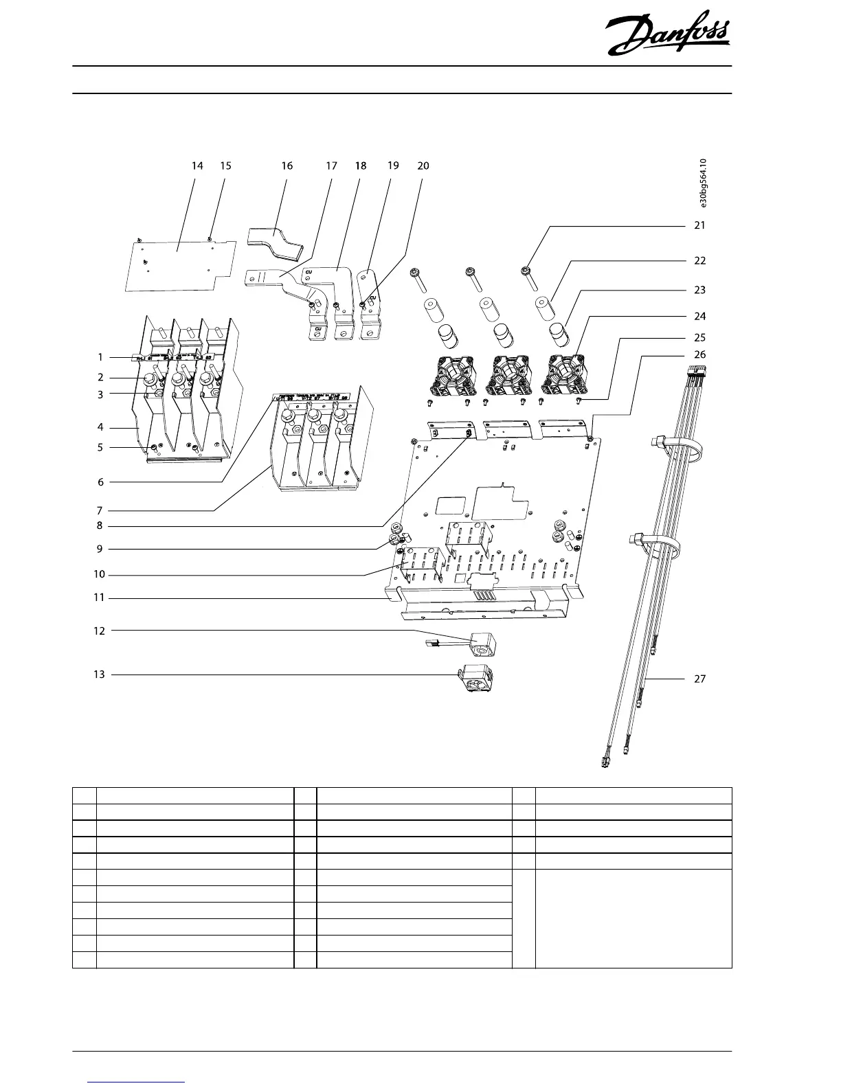
1.4 Assembly Guidelines
1 R/S/T terminal label 12 Mixing fan 23 Nomex tube
2 M10x30 machine screw 13 Mixing fan housing 24 Current sensor
3 M10 nut 14 EMC shield 25 M4x10 thread-forming screw
4 Mains input terminal block 15 Plastic mounting button 26 M5 nut
5 M5x12 machine screw 16 Busbar insulator sleeve 27 Wire harness (current sensor cables)
6 U/V/W terminal label 17 Motor busbar, U – Not shown: multiple wire guide, wire
routing clip, M5x11 thread-cutting screw,
power terminal mounting plate (IP20/
Chassis), and IGBT busbars (in 300 A
current sensor kit only).
7 Motor terminal block 18 Motor busbar, V
8 Cable retaining clip 19 Motor busbar, W
9 M10 nut with captive washer 20 M5x16 torx screw
10 Cable clamp adapter 21 M8x70 screw
11 Power terminal mounting plate (IP21/IP54) 22 Cylinder busbar
Illustration 1.4 Exploded View of 500 A Current Sensor Kit
Installation Instructions
300 A/500 A Current Sensor Kit for D2h/D4h/D7h/D8h Drives
VLT
®
FC Series FC 102, FC 103, FC 202, FC 302
6
Danfoss A/S © 07/2018 All rights reserved. MI70V202
 Loading...