1.4.1 Installing Current Sensors
NOTICE
MOUNTING PLATE SELECTION
The kit includes 2 power terminal mounting plates, select
the correct plate for the enclosure. Illustration 1.4 shows the
plate for IP20/Chassis enclosures. Illustration 1.5 shows the
plate for IP21/Type 1 and IP54/Type 12 enclosures.
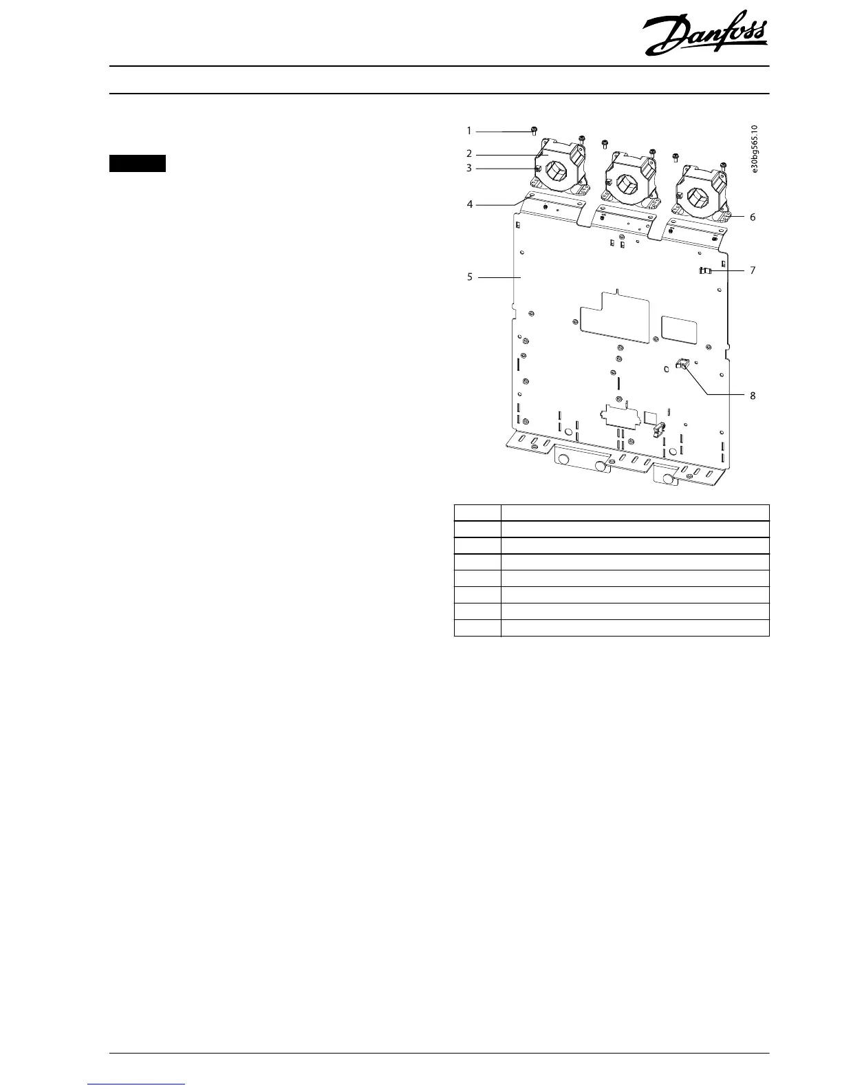
1. Position 3 current sensors on top of the power
terminal mounting plate so that the cable connectors
face the back of the drive. Ensure that the airow
arrows on the sensors point toward the front of the
drive.
2. Secure 6 M4x10 thread-forming screws (T20), 2 in the
base of each current sensor. Torque to 2.0 Nm
(17.7 in-lb).
3. Connect the wire harness to the current sensors, 1
cable to each current sensor.
4. Route the cables through the cable guides.
1 M4x10 thread-forming screw
2Current sensor
3 Current sensor cable connector
4Mounting hole
5 Power terminal mounting plate
6Mounting hole
7Wire guide
8Cable clip
Illustration 1.5 Back View of Power Terminal Mounting Plate and
Current Sensors
Installation Instructions
300 A/500 A Current Sensor Kit for D2h/D4h/D7h/D8h Drives
VLT
®
FC Series FC 102, FC 103, FC 202, FC 302
MI70V202 Danfoss A/S © 07/2018 All rights reserved.
7
 Loading...