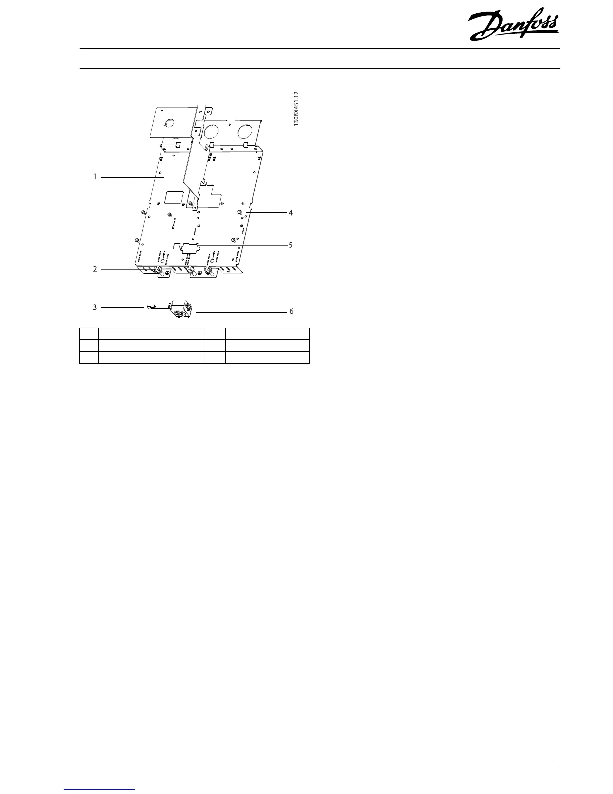
1 Power terminal mounting plate 4 Screw (T25)
2 Nut (8 mm) 5 Mixing fan slot
3 Mixing fan cable 6 Mixing fan and housing
Illustration 1.3 Power Terminal Mounting Plate
1. Remove 5 thread-cutting screws (T25) from the top
of the plate. The fan screw can remain in place, if
present.
2. Remove 2 nuts (8 mm).
3. Release the current sensor cables from the current
sensors.
4. Unplug the wire harness from the power card, and
discard it.
5. Lift the power terminal mounting plate and unplug
the mixing fan cable that is located under the plate.
6. Remove the power terminal mounting plate with the
old current sensors attached and discard it.
Installation Instructions
300 A/500 A Current Sensor Kit for D2h/D4h/D7h/D8h Drives
VLT
®
FC Series FC 102, FC 103, FC 202, FC 302
MI70V202 Danfoss A/S © 07/2018 All rights reserved.
5
 Loading...