14 Technical data, DHP-L
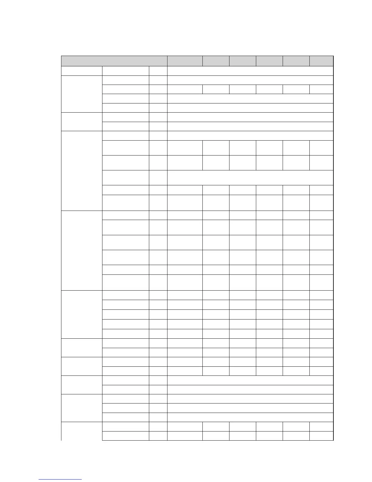
Table 47. Technical data
DHP-L 4 6 8 10 12 16
Type Brine/water
Refrigerant Type R407C
Amount kg 0,75 1,20 1,30 1,45 1,55 2,00
Test pressurisation MPa 3,4
Design pressure MPa 3,1
Compressor Type Scroll
Oil POE
Electrical data
3-N, ~50 Hz
Mains power supply V 400
Rated output, com-
pressor
kW 2,7 3,0 3,2 4,2 5,0 7,2
Rated output, circu-
lation pumps
kW 0,2 0,2 0,2 0,5 0,5 0,6
Auxiliary heater, 3
step
kW 3/6/9
Start current
3
A 17 12 10 18 17 18
Fuse A
16
9
/10
4
/10
5
/16
6
10
4
/16
5
/20
6
16
4
/16
5
/20
6
16
4
/16
5
/20
6
16
4
/20
5
/25
6
20
4
/20
5
/2
5
6
Electrical data
1-N, ~50 Hz
Mains power supply V 230 230 230 230 230 *
Rated output, com-
pressor
kW 2,7 3,2 3,6 4,5 5,5 *
Rated output, circu-
lation pumps
kW 0,2 0,2 0,2 0,5 0,5 *
Auxiliary heater, 3
step
kW 1,5/3,0/4,5 1,5/3,0/4,5 1,5/3,0/4,5 1,5/3,0/4,5 1,5/3,0/4,5 *
Start current
3
A 17 11 21 26 28 *
Fuse A
20
4
/25
5
/32
6
25
4
/32
5
/40
6
25
4
/32
5
/40
6
32
4
/40
5
/50
6
32
4
/40
5
/50
6
*
Performance
10
Heat factor
1
kW 3,52 5,33 7,51 9,40 11,0 16,4
COP
1
3,90 4,04 4,34 4,24 4,20 3,99
Heat factor
2
kW 3,42 5,38 7,40 9,24 10,6 15,6
COP
2
3,05 3,41 3,57 3,51 3,39 3,19
Incoming power
1
kW 0,9 1,3 1,7 2,2 2,6 4,1
Nominal flow
8
Cooling circuit l/s 0,20 0,36 0,49 0,62 0,71 1,02
Heating circuit l/s 0,09 0,14 0,19 0,24 0,28 0,39
External available
pressure
7
Cooling circuit kPa 38 35 32 76 69 37
Heating circuit kPa 51 48 44 39 58 54
Max/Min temper-
ature
Cooling circuit °C 20/-10
Heating circuit °C 55/20
Pressure
switches
Low pressure MPa 0,08
Operation MPa 2,85
High pressure MPa 3,10
Water volume Water heater l * * * * * *
Condenser l 0,8 1,6 1,9 2,1 2,1 2,9
68 – Service instructions VMGFC302
 Loading...


