17 Technical data, DHP-C
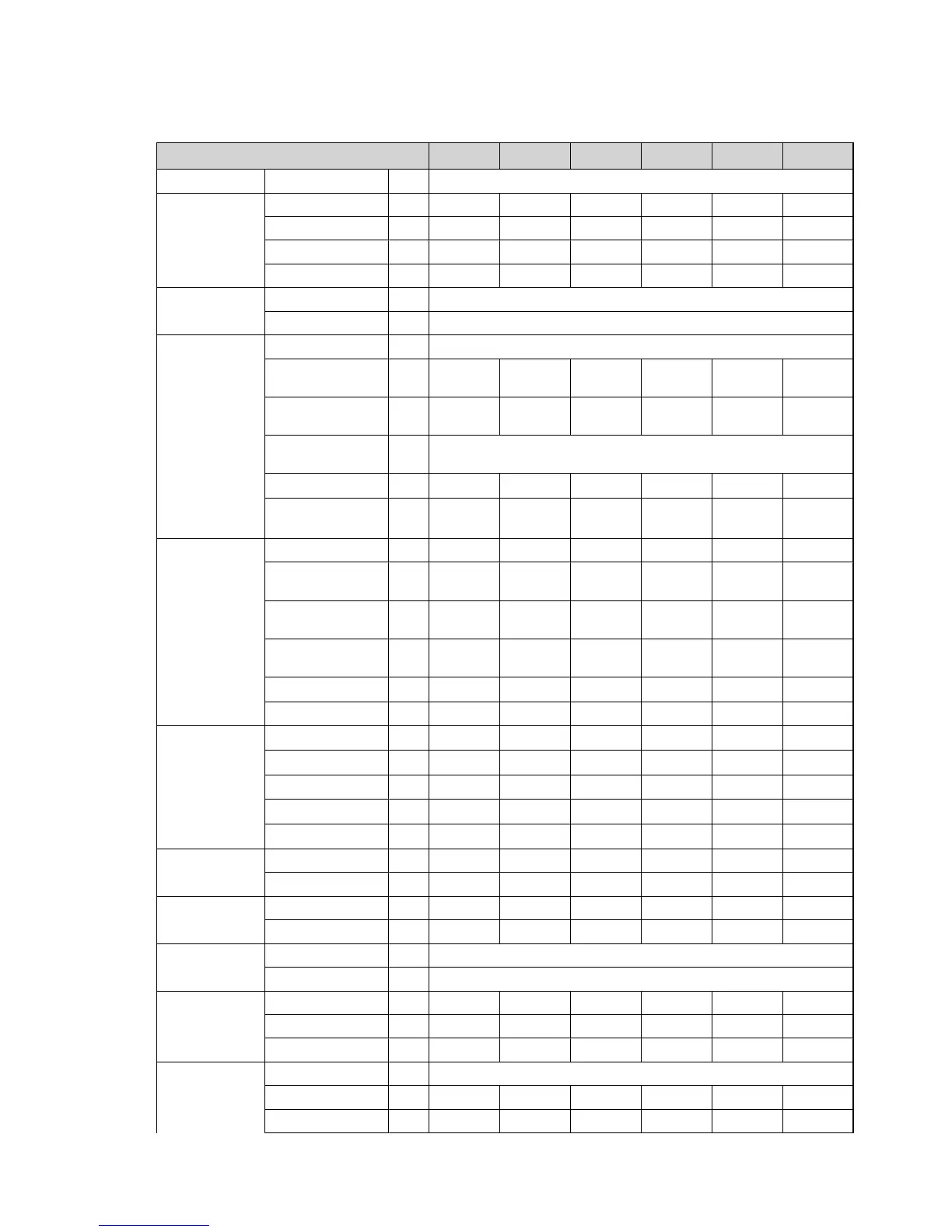
Table 50. Technical data
DHP-C 6 8 10 4H 5H 7H
Type Brine/water
Refrigerant Type R407C R407C R407C R134a R134a R134a
Amount kg 1,20 1,30 1,45 0,90 1,00 1,10
Test pressurisation MPa 3,4 3,4 3,4 3,2 3,2 3,2
Design pressure MPa 3,1 3,1 3,1 2,45 2,45 2,45
Compressor Type Scroll
Oil POE
Electrical data
3-N, ~50 Hz
Mains power supply V 400
Rated output, com-
pressor
kW 3,0 3,2 4,2 3,0 3,2 4,2
Rated output, circu-
lation pumps
kW 0,2 0,2 0,5 0,2 0,2 0,3
Auxiliary heater, 3
step
kW 3/6/9
Start current
3
A 12 10 18 12 10 18
Fuse A
10
4
/16
5
/20
6
16
4
/16
5
/20
6
16
4
/16
5
/20
6
10
4
/16
5
/20
6
16
4
/16
5
/20
6
16
4
/16
5
/20
6
Electrical data
1-N, ~50 Hz
Mains power supply V * * * * * *
Rated output, com-
pressor
kW * * * * * *
Rated output, circu-
lation pumps
kW * * * * * *
Auxiliary heater, 3
step
kW * * * * * *
Start current
3
A * * * * * *
Fuse A * * * * * *
Performance
10
Heat factor
1
kW 5,33 7,51 9,40 - - -
COP
1
4,04 4,34 4,24 - - -
Heat factor
2
kW 5,38 7,40 9,24 3,20 4,50 5,50
COP
2
3,41 3,57 3,51 2,70 2,90 2,90
Incoming power
1
kW 1,3 1,7 2,2 - - -
Nominal flow
8
Cooling circuit l/s 0,36 0,49 0,62 0,20 0,28 0,37
Heating circuit l/s 0,14 0,19 0,24 0,08 0,12 0,14
External available
pressure
7
Cooling circuit kPa 35 32 76 37 54 60
Heating circuit kPa 48 44 39 48 50 43
Max/Min temper-
ature
Cooling circuit °C 20/-10
Heating circuit °C 55/20
Pressure switches Low pressure MPa 0,08 0,08 0,08 0,03 0,03 0,03
Operation MPa 2,85 2,85 2,85 1,80 1,80 1,80
High pressure MPa 3,10 3,10 3,10 2,45 2,45 2,45
Water volume Water heater l 180
Condenser l 1,6 1,9 2,1 1,6 1,9 2,1
Evaporator l 0,7 1,2 1,6 0,7 1,2 1,6
74 – Service instructions VMGFC302
 Loading...


