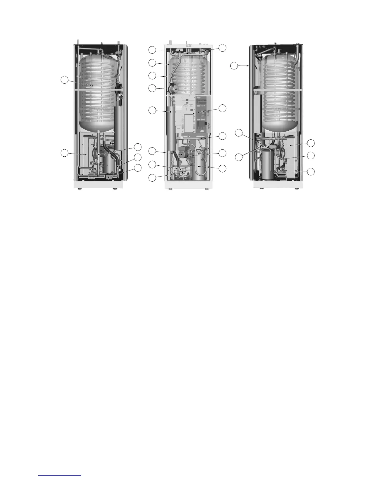
Figure 8. Components
Symbol explanation
1 Water heater, 180 litres 13 Brine out
2 Defrosting tank 14 Hot water temperature sensor (displays maximum tem-
perature)
3 Evaporator, insulated 15 Control panel for control equipment
4 Exchange valve, defrosting 16 Electrical panel
5 Exchange valve, heating system 17 Heating system supply line
6 Supply line sensor 18 Compressor
7 Heating system circulation pump 19 Low pressure switch
8 Auxiliary heating, immersion heater 20 Operating pressure switches
9 Circulation pump coolant system 21 High pressure switch
10 Brine in 22 Condenser with primary side drain
11 Drying filter 23 Return pipe sensor, heating system
12 Expansion valve 24 Brine in to defrosting tank during defrosting
Service instructions VMGFC302 – 15
 Loading...