EasyManuals Logo
Home>Danfoss>Controller>ECL Comfort 310

Danfoss ECL Comfort 310 Service Guide

Danfoss ECL Comfort 310
16 pages
To Next Page IconTo Next Page
To Previous Page IconTo Previous Page
Page #7 background imageLoading...
Page #7 background image
© Danfoss | 2017.06 | 7
VI.LV.H1.02
Service guide ECL 296 / ECL 310 Modbus
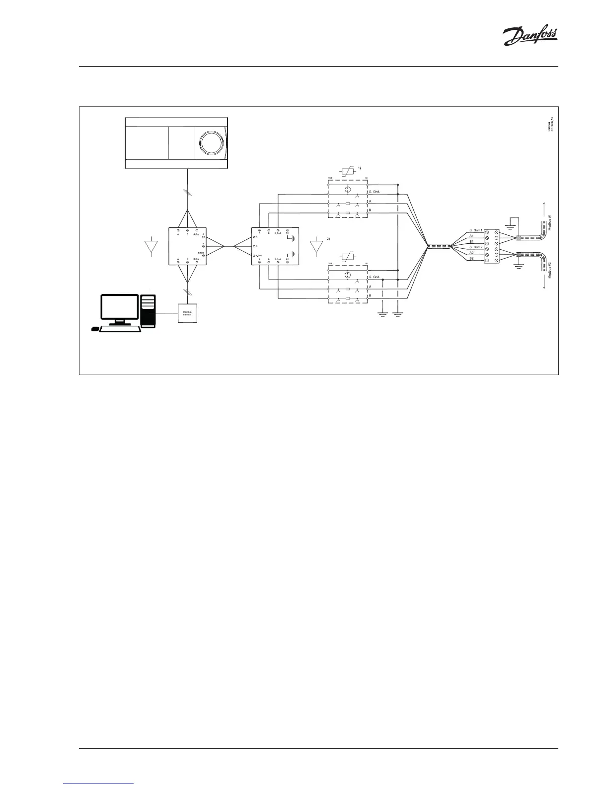
7.1 Central heating station
1) = surge protector 2) = repeater
Note:
a)
Repeater channels are isolated. Based on the central heating
station architecture, more than one network (like left wing, right
wing) is possible. Single point earthing on common reference
signal (S.Gnd) and shield cable to be maintained (Refer section 5
point 5, 6).
Dot on the intersection lines (S.Gnd, Earth) means that those two
signals are electrically shorted.
Surge suppressor connection should match as in section 8.2.

Other manuals for Danfoss ECL Comfort 310

Questions and Answers:

Question and Answer IconNeed help?

Do you have a question about the Danfoss ECL Comfort 310 and is the answer not in the manual?

Danfoss ECL Comfort 310 Specifications

General IconGeneral
BrandDanfoss
ModelECL Comfort 310
CategoryController
LanguageEnglish

Related product manuals