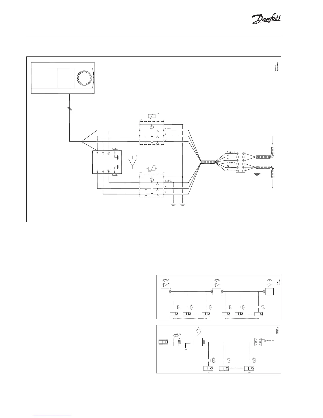
7.2 Repeater stations (individual houses with repeater)
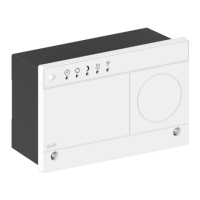
1) = surge protector 2) = repeater
Note:
a)
Normally repeaters’ inputs and outputs are isolated. Check the
resistance between input common reference signal (S.Gnd1) and
output common reference signal (S.Gnd2) using multimeter.
If signals are having >1 Mohm, then connect the output side com-
mon reference signal to earth.
Input cable (coming from central heating station) shield MUST be
oating and output cable shield is connected to earth.
This is to maintain single point earthing in each network, on com-
mon reference signal (S.Gnd) and shield cable (Refer section 5 point
5, 6).
Dot on the intersection lines (S.Gnd, Earth) means that those two
signals are electrically shorted.
b)
Internal termination of repeaters can be switched ON if the con-
nection matches with section 5 point 4.a
c)
Internal termination of repeaters is switched OFF if the connec-
tion matches with section 5 point 4.b
1) = surge protector
2) = repeater
3) = line termination (LT)
 Loading...