1.
2.
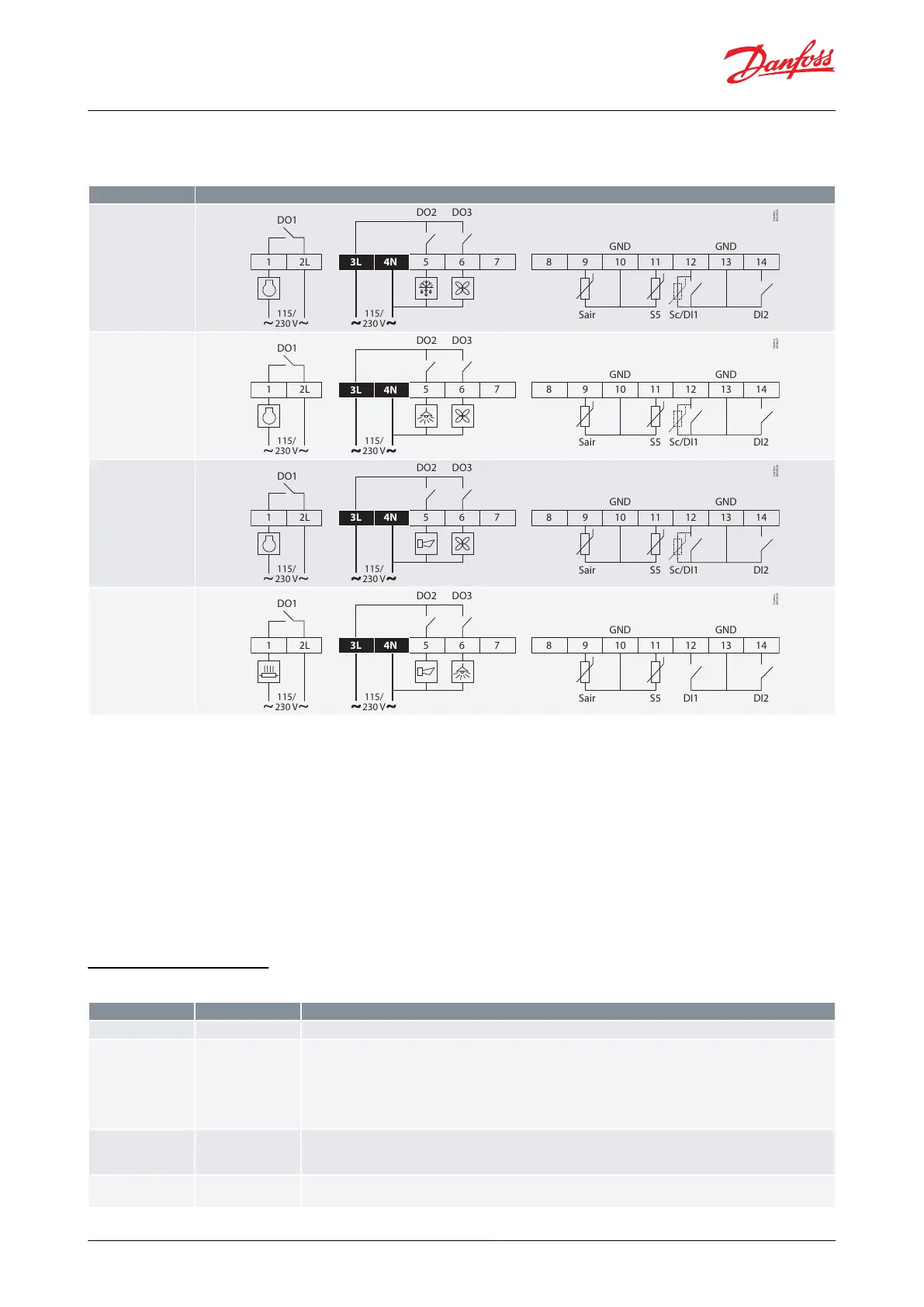
EKC 223
Table 4: The electrical wiring diagrams for the selection of 4 applications
DO1
1
Sair S5 Sc/DI1 DI2
DO2 DO3
GND GND
Danfoss
80G8436
5
6
7
3L 4N
10
11
12 13
14
8 92L
115/
230 V
115/
230 V
DO1
1
Sair S5 Sc/DI1 DI2
DO2 DO3
GND GND
Danfoss
80G8437
5
6
7
3L 4N
10
11
12 13
14
8 92L
115/
230 V
115/
230 V
DO1
1
Sair S5 Sc/DI1 DI2
DO2 DO3
GND GND
Danfoss
80G8438
5
6
7
3L 4N
10
11
12 13
14
8 92L
115/
230 V
115/
230 V
DO1
1
Sair S5 DI1 DI2
DO2 DO3
GND GND
Danfoss
80G8439
5
6
7
3L 4N
10
11
12 13
14
8 92L
115/
230 V
115/
230 V
NOTE:
Cables for sensors, DI inputs and data communication must be kept separate from other high voltage cables to
avoid electric noises.
◦ Use separate cable trays
◦ Keep a distance between cables of at least 10 cm
◦ Long cables at the DI input should be avoided
Do not use excessive force while securing wires in to the connectors, allowed tightening torque and wire sizes
are:
◦ Power connectors: wire size = 0.5 – 1.5 mm
2
, max. tightening torque = 0.4 Nm
◦ Low voltage signal connectors: wire size = 0.15 – 1.5 mm
2
, max. tightening torque = 0.2 Nm
◦ 2L and 3L must be connected to the same phase
Electrical connections
Table 5: Connection details
115 V AC / 230 V AC / 50/60 Hz (refer to the controller label)
Temperature sensor inputs:
• Sair, Air temperature sensor
• S5 Evaporator sensor
Sensor types:
Pt 1000 (AKS11), PTC 1000 (EKS111), NTC5K (EKS211), NTC10K (EKS221).
All sensors must be of the same type.
Digital input signal
The dened function is active when the input is short-circuited or opened, depending on the function dened in o02.
Note: DI1 can also be used for a Sc Condenser sensor
Digital input signal
The dened function is active when the input is short-circuited or opened, depending on the function dened in o37.
© Danfoss | Climate Solutions | 2023.05 BC432222569027en-000201 | 13
Case controller, type EKC 223 and EKC 224
 Loading...