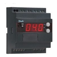
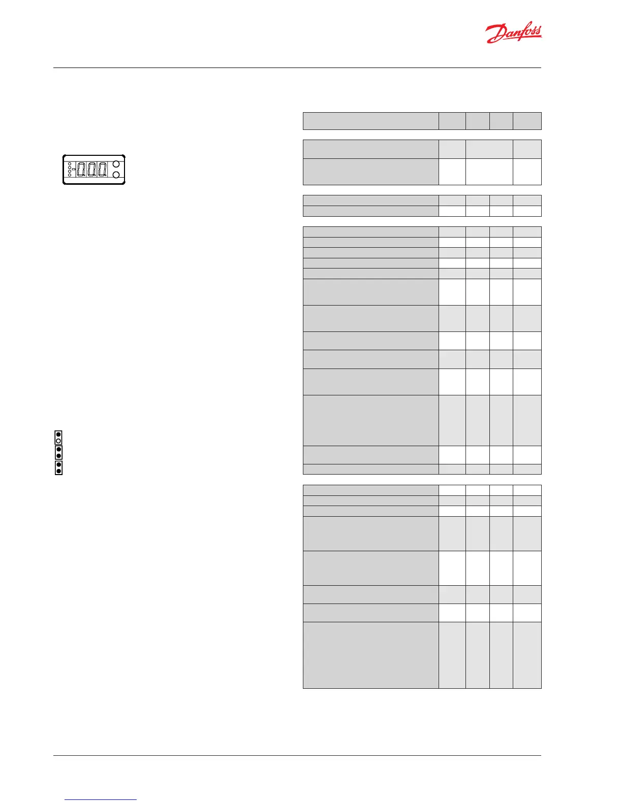
Display
The values will be shown with three digits, and with a setting you
can determine whether the temperature are to be shown in °C or
in °F. (Pressure in bar or psig.)
Light-emitting diodes (LED) on front panel
There are LED’s on the front panel which will light up when the
belonging relay is activated.
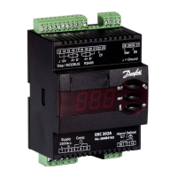
The uppermost LED will indicate when the valve is moving
towards a greater opening degree.
The next LED will indicate when the valve is moving towards a
smaller opening degree.
All light-emitting diodes will ash when there is an error in the
regulation.
In this situation you can upload the error code on the display and
cancel the alarm by giving the uppermost button a brief push.
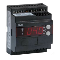
The buttons
When you want to change a setting, the two buttons will give
you a higher or lower value depending on the button you are
pushing. But before you change the value, you must have access
to the menu. You obtain this by pushing the upper button for a
couple of seconds - you will then enter the column with parameter
codes. Find the parameter code you want to change and push
the two buttons simultaneously. When you have changed the
value, save the new value by once more pushing the two buttons
simultaneously.
Gives access to the menu (or cutout an alarm)
Gives access to changes
Saves a change
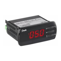
Examples of operations
Set one of the other menus
1. Push the upper button until a parameter is shown
2. Push one of the buttons and nd the parameter you want to
change
3. Push both buttons simultaneously until the parameter value is
shown
4. Push one of the buttons and select the new value
5. Push both buttons again to conclude the setting
SW =1.2x
Function Param. Min. Max.
Fac.
setting
Normal display
Shows the actual superheat/ valve's opening
degree/ temperature. Dene view in o17
- K
If you wish to see the expansion valve’s actual
opening degree, give the lower button a brief
push (1s). Dene view in o17
- %
Reference
Units (0=°C+bar / 1=°F+psig) r05 0 1 0
Start/stop of refrigeration r12 OFF On 1
Regulating parameters
P: Amplication factor Kp n04 0.5 20 3
I: Integration time T n05 30 s 600 s 120
Max. value of superheat reference n09 2 K 30 K 10
Min. value of superheat reference n10 1 K 12 K 4
MOP n11 0.0 bar 20 bar 20
Signal reliability during start-up. Safety time
period.
Should only be changed by trained sta.
n15 0 s 90 s 0
Signal reliability during start-up – Opening
degree’s start value. Should only be changed
by trained sta
n17 0% 100% 0
Amplication factor for superheat
Changes should only be made by trained sta
n20 0.0 10.0 0,4
Value of min. superheat reference for loads
under 10%
n22 1 K 15 K 2
”n37” and ”n38” are adapted to valve type ETS
50 and should only be changed through the
use of another valve
Number of steps from 0-100% opening degree
(x10)
(ETS 50=263, ETS 100=353)
ETS 12.5, ETS 25, ETS 50=263
ETS 100=353
ETS 250, ETS 400=381
n37
000
stp*
5000
stp *
263
Number of steps per second n38
10
stp/s
300
stp/s
250
Integration time for inner loop (TnT0) n44 10 s 120 s 30
Miscellaneous
Controller’s address o03 *) 1 60
ON/OFF switch (service-pin message) o04 *) - -
Set supply voltage frequency o12 50 Hz 60 Hz 50
Select display for ”normal picture”
1: Superheat
2: Valve’s opening degree
3: Air temperature
o17 1 3 1
Manual control of outputs:
OFF: no manual control
3: Alarm relay activated (cut out)
At settings 3, ”o45” will be active
o18 off 3 0
Working range for pressure transmitter – min.
value
o20 -1 bar 60 bar -1.0
Working range for pressure transmitter – max.
value
o21 -1 bar 60 bar 12
Refrigerant setting
1=R12. 2=R22. 3=R134a. 4=R502. 5=R717.
6=R13. 7=R13b1. 8=R23. 9=R500. 10=R503.
11=R114. 12=R142b. 13=User dened.
14=R32. 15=R227. 16=R401A. 17=R507.
18=R402A. 19=R404A. 20=R407C. 21=R407A.
22=R407B. 23=R410A. 24=R170. 25=R290.
26=R600. 27=R600a. 28=R744. 29=R1270.
o30 0 29 0
*) The display on the controller can show 3 digits only, but the setting
value has 4 digits. Only the 3 most important will be shown.
It means f.ex. . 250 will give a setting of 2500.
Operation Menu survey

 Loading...