8 User Guide RS8FZ402 © Danfoss 2015-07 EKC 313
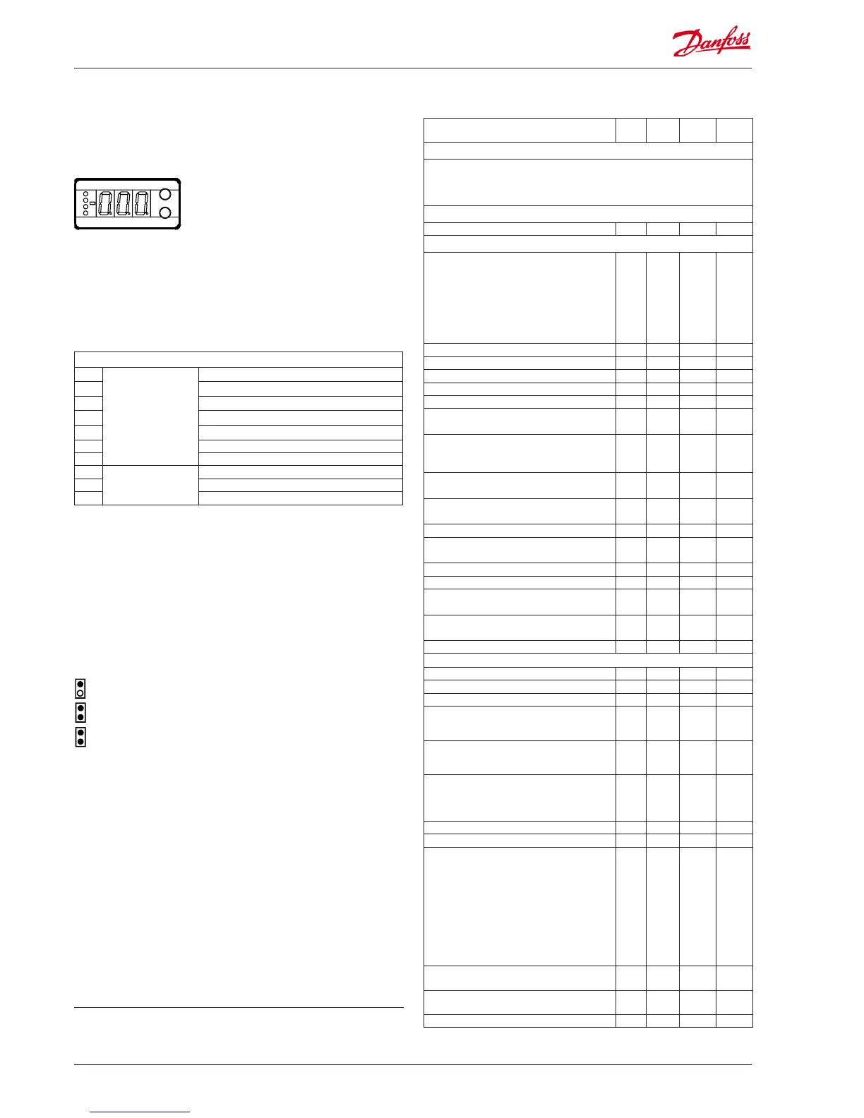
Light-emitting diodes (LED) on front panel
All 4 light-emitting diodes will ash when there is an error in the
regulation.
In this situation you can upload the error code on the display and
cancel the alarm by giving the uppermost button a brief push.
The controller can give the following messages:
E1
Error message
Fault in controller
E15
Cut-out S2 sensor
E16 Short circuited S2 sensor
E17 Cut-out S3 sensor
E18
Short circuited S3 sensor
E20 Fault on signal from Pc
E39 Fault on signal from P0
A11
Alarm message
No refrigerant has been selected
A43 Step motor fault. Output or phase
A45 Regulation stopped. Main switch r12 = o
Display
The values will be shown with three digits.
Temperature are shown in °C and pressure in bar.
Operation
Menu survey
The buttons
When you want to change a setting, the two buttons will give you
a higher or lower value depending on the button you are push-
ing. But before you change the value, you must have access to the
menu. You obtain this by pushing the upper button for a couple
of seconds - you will then enter the column with parameter codes.
Find the parameter code you want to change and push the two
buttons simultaneously. When you have changed the value, save
the new value by once more pushing the two buttons simultane-
ously.
Gives access to the menu
(or cutout an alarm)
Gives access to changes
Saves a change
Examples of operations
Set of a menu
1. Push the upper button until a parameter is shown
2. Push one of the buttons and nd the parameter you want to
change
3. Push both buttons simultaneously until the parameter value is
shown
4. Push one of the buttons and select the new value
5. Push both buttons again to conclude the setting
Function
Para-
meter
Min. Max.
Fac.set-
ting
Normal display
Displays either the valve's current opening degree or the current superheat value.
(Can be set in o17)
Briey pushing the bottom button will display one of the two readings.
Briey pushing both buttons will display the superheat reference (u22).
Start / stop
Start / stop af regulation r12 OFF (0) On (1) On (1)
Regulating parameters
Select valve type:
0=ETS 12,5 & 25 / CCM10 & CCM20
1=ETS 50 / CCM30, 2=ETS 100 / CCM40
3=ETS 250, 4=ETS 400,
5=User dened (set : n37 and n38)
6=0-10 V's output must control ICAD actuator
7=0-10 V's output must on/o control a solid
state relay.
n03 0 7 0
I: Integration time Tn n05 5 s 600 s 90
D: Dierentiation time Td n06 0 s 60 s 0
Max. value of superheat reference n09 3 K 60 K 40
Min. value of superheat reference n10 3 K 40 K 10
MOP (max. = O ) n11 0 bar 60 bar 60
Signal reliability during start-up. Time for safety.
Should only be changed by trained sta
n15 0 s 240 s 0
Signal reliability during start-up – Opening
degree’s start value. Should only be changed by
trained sta.
n17 0% 100% 0
Kp amplication just around reference value
Changes should only be made by trained sta
n19
0 30 3
Amplication factor for superheat. (KpT
0
)
Changes should only be made by trained sta
n20 0 30 5
Max. opening degree of valve n32 0% 100% 100
Number of steps from 0-100% opening degree
(x10) **
n37 0 500 263
Number of steps per second n38 0 300 250
Max. Kp factor for PID-regulation (Kp max) n95 0 30 5
Calculation factor for superheat SH
Changes should only be made by trained sta
n96 10 100 50
Filter constant for SH reference
Changes should only be made by trained sta
n97 5 s 600 s 60
Lower limit value for the condensing pressure n98 -30°C 10°C -5
Miscellaneous
Controller’s address (0 = o ) o03* 0 119 0
ON/OFF switch (service-pin message) o04* - - -
Set supply voltage frequency o12 50Hz (0)60 Hz (1) 0
Select display view for the "normal display"
1: Opening degree of the valve
2: Superheat
o17 1 2 1
Manual control of outputs:
0: Normal regulation
1: Overriding. Manual control permitted
o18 0 1 0
Pressure transmitter selection
1: AKS 32R / AKS 2050
2: Pressure transmitter with 0-10 V
3: Pressure transmitter with 1-5 V
o10 1 3 1
Working range for pressure transmitter Pc - min. o20 -1 bar 5 bar -1
Working range for pressure transmitter Pc - max. o21 6 bar 199 bar 59
Refrigerant setting for P0 circuit
1=R12. 2=R22. 3=R134a. 4=R502. 5=R717.
6=R13. 7=R13b1. 8=R23. 9=R500. 10=R503.
11=R114. 12=R142b. 13=User dened.
14=R32. 15=R227. 16=R401A. 17=R507.
18=R402A. 19=R404A. 20=R407C. 21=R407A.
22=R407B. 23=R410A. 24=R170. 25=R290.
26=R600. 27=R600a. 28=R744. 29=R1270.
30=R417A. 31=R422A. 32=R413A. 33=R422D.
34=R427A. 35=R438A
o30 0 35 0
Relay application: 0=Alarm relay. 1=EVR valve i
liquid line
o36 0 1 0
Forced control of the valves opening degree.
(Only if o18 is set to manual)
o45 0 100% 0
Working range for pressure transmitter P0 - min. o47 -1 bar 5 bar -1
SW =2.0x
*) This setting will only be possible if a data communication module has been installed in the
controller.
**) The display on the controller can show 3 digits only, but the setting value has 4 digits. Only the
3 most important will be shown. It means fx. 250 will give a setting of 2500.

 Loading...