ENGLISH
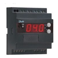
Light-emitting diodes (LED) on front panel
There are LED’s on the front panel which will light up when the
belonging relay is activated.
The upper LED will indicate the valve’s opening degree. A short
pulse indicates a small liquid flow and a long pulse a heavy liquid
flow. The other LED will indicate when the controller calls for
refrigeration.
The three lowermost LED’s will flash, if there is an error in the regu-
lation.
In this situation you can upload the error code on the display and
cancel the alarm by giving the uppermost button a brief push.
Display
The values will be shown with three digits, and with a setting you
can determine whether the temperature are to be shown in °C or
in °F.
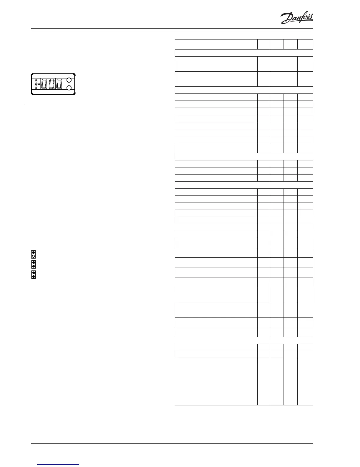
Operation Menu survey
The buttons
When you want to change a setting, the two buttons will give you
a higher or lower value depending on the button you are push-
ing. But before you change the value, you must have access to the
menu. You obtain this by pushing the upper button for a couple
of seconds - you will then enter the column with parameter codes.
Find the parameter code you want to change and push the two
buttons simultaneously. When you have changed the value, save
the new value by once more pushing the two buttons simultane-
ously.
Gives access to the menu
(or cutout an alarm)
Gives access to changes
Saves a change
Examples of operations
Set set-point
1. Push the two buttons simultaneously
2. Push one of the buttons and select the new value
3. Push both buttons again to conclude the setting
Set one of the other menus
1. Push the upper button until a parameter is shown
2. Push one of the buttons and find the parameter you want to
change
3. Push both buttons simultaneously until the parameter value is
shown
4. Push one of the buttons and select the new value
5. Push both buttons again to conclude the setting
SW = 1.4x
Factory setting
If you need to return to the factory-set values, it can be done in this way:
- Cut out the supply voltage to the controller
- Keep both buttons depressed at the same time as you recon nect the supply voltage
Function
Para-
meter
Min. Max.
Factory
setting
Normal display
Shows the actual superheat/ valve's opening
degree/ temperature
Define view in o17
- K
Temperature, superheating, or the temp. reference
is displayed if the bottom button is pressed briefly.
Define view in o17
- %
Reference
Set the requirede set point - -60°C 50°C 10
Differential r01 0.1 K 20 K 2.0
Units (0=°C+bar /1=°F+psig) r05 0 1 0
External contribution to the reference r06 -50 K 50 K 0
Correction of signal from S2 r09 -50.0 K 50.0 K 0.0
Correction of signal from S3 r10 -50.0 K 50.0 K 0.0
Start / stop of refrigeration r12 OFF On 1
Define thermostat function
(0= no thermostat function, 1=On/off thermostat)
r14 0 1 0
Alarm
Upper deviation (above the temperature setting) A01 3.0 K 20 K 5.0
Lower deviation (below the temperature setting) A02 1 K 10 K 3.0
Alarm’s time delay A03 0 min. 90 min. 30
Regulating parameters
P: Amplification factor Kp n04 0.5 20 3.0
I: Integration time T n05 30 s 600 s 120
D: Differentiation time Td (0 = off) n06 0 s 90 s 0
Max. value of superheat reference n09 2 K 50 K 6
Min. value of superheat reference n10 1 K 12 K 4
MOP (max = off) n11 0.0 bar 60 bar 60
Period time (only when AKV/A valve is used) n13 3 s 10 s 6
Stability factor for superheat control.
Changes should only be made by trained staff
n18 0 10 5
Damping of amplification around reference value
Changes should only be made by trained staff
n19 0.2 1.0 0.3
Amplification factor for superheat
Changes should only be made by trained staff
n20 0.0 10.0 0.4
Definition of superheat control
1=MSS, 2=LOADAP
n21 1 2 1
Value of min. superheat reference for loads under
10%
n22 1 15 2
Standby temperature when valve closed (TQ valve
only)
Changes should only be made by trained staff
n26 0 K 20 K 0
Standby temperature when valve open (TQ valve
only)
Changes should only be made by trained staff
n27 -15 K 70 K 20
Max. opening degree
Changes should only be made by trained staff
n32 0 100 100
Min. opening degree
Changes should only be made by trained staff
n33 0 100 0
Miscellaneous
Controller’s address o03* 0 119 -
ON/OFF switch (service-pin message) o04* - - -
Define valve and output signal:
0: Off
1: TQ. AO: 0-20 mA
2: TQ. AO: 4-20 mA
3: AKV, AO: 0-20 m
4: AKV, AO: 4-20 mA
5: AKV, AO: EKC 347-SLAVE
6: ICM, AO: 0-20 mA / ICM OD%
7: ICM, AO: 4-20 mA / ICM OD%
o09 0 7 0
 Loading...