© Danfoss | DCS (az) | 2018.06
DKRCC.PI.RS0.C6.02 | 2
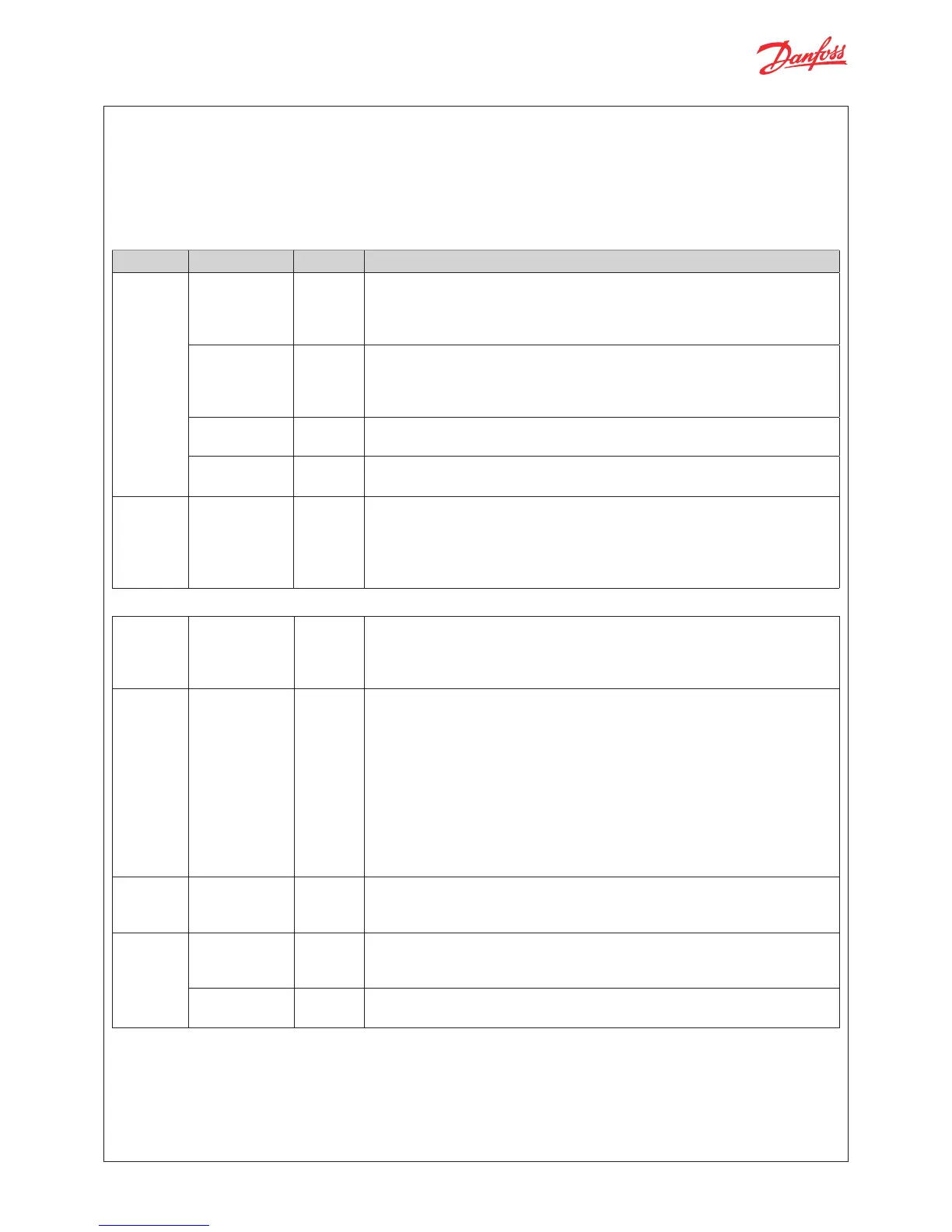
I/O TYPE NUMBER SPECIFICATION
Analog
inputs
Max. 15 V input voltage
Do not connect voltage sources to unpowered units without limiting the current
to analog inputs (overall 80 mA).
Open circuit HW diagnostics available for voltage input on : AI4
Voltage 2
AI3 (Pe)
0 – 5 V ratiometric,
AI4
0 – 5 V , 0 – 10 V
NTC 2
AI1 (S3, S4), AI2 (S2)
NTC temperature probes, 10 kΩ at 25 °C
Auxiliary
Supplies
1
5 V +
Sensor supply: 5 V DC / 15 mA, overload protection approximately 150 mA
Digital
inputs
Voltage free
contacts
2
DI1, DI2
Steady current minimum 1mA
Cleaning current 100 mA at 15 V DC
On: RIL < = 300 Ω
Off: RIH > = 3.5 k Ω
TECHNICAL SPECIFICATIONS
Digital
output
Relay 1
C1-NO1
Normally Open: 3 A General purpose, 250 V AC, 100 k cycle
Normally Open: 3 A Inductive (AC-15), 250 V AC, 100 k cycle
Normally Closed: 2 A General purpose, 250 V AC, 100 k cycle
Stepper
motor
Bipolar /
unipolar
1
Stepper valves: A1, A2, A3, A4
Bipolar and unipolar stepper motor output:
- Danfoss ETS / KVS / ETS C / KVS C / CCMT 2 – CCMT 42 / CTR Valves
(green, red, black, white)
- ETS6 / CCMT 0 / CCMT 1 (black, red, yellow, orange)
Other Valves:
- speed 10 – 400 pps
- drive mode 1/8 microstep
- max. peak phase current: 1.2 A (848 mA RMS)
- max. drive voltage 40 V
- max. output power 12 W
Battery
backup
1
VBATT: 18 – 24 V DC (24 V DC recommended):
– max. battery current: 850 mA at 18 V
– battery alarm will be activated below 16 V DC and above 27 V DC
Communi-
cation
RS-485 RTU 1
RS485
Galvanic isolation
No Built-in termination
CAN 1
CAN - RJ
RJ connector to directly connect and supply a MMI
POWER SUPPLY
EKE has galvanic isolation by switch-mode power supply.
24 V AC ± 20 %, 50/60 Hz. Maximum power consumption: 18 VA.
Input voltage rating (DC): 24 V DC ± 20%, 15 W.

 Loading...