Option - either part may exist Clean area or part
Superseded - parts are not interchangeable Be careful not to scratch or damage
Measurement required Note correct orientation
Flatness specification Mark orientation for reinstallation
Parallelism specification Torque specification
External hex head Press in - press fit
Internal hex head Pull out with tool – press fit
Torx head Cover splines with installation sleeve
O-ring boss port Pressure measurement/gauge location or
specification
The symbols above appear in the illustrations and text of this manual. They are intended to communicate
helpful information at the point where it is most useful to the reader. In most instances, the appearance
of the symbol itself denotes its meaning. The legend above defines each symbol and explains its purpose.
Design
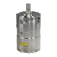
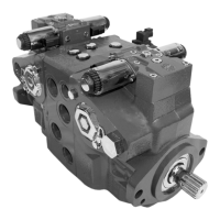
Danfoss H1 tandem closed circuit piston pumps convert input torque to hydraulic power. The tandem
design powers two independent drive trains for dual-path propel applications. The two-piece input shaft
transmits rotational force to the cylinder block. A splined coupling connects the front and rear shafts.
Bearings at the front, rear, and center of the pump support the shaft. Splines connect each shaft to a
cylinder block. A lip-seal at the front end of the pump prevents leakage where the shaft exits the pump
housing. The spinning cylinder block contains nine reciprocating pistons. Each piston has a brass slipper
connected at one end by a ball joint. The block spring, ball guide, and slipper retainer hold the slippers to
the swashplate. The reciprocating movement of the pistons occurs as the slippers slide against the
inclined swashplates during rotation. Via the valve plates, one half of each cylinder block is connected to
port A or C and the other half to port B or D. Front and rear sections have independent porting in the
center section. As each piston cycles in and out of its bore, fluid is drawn from one port and displaced to
the other thereby imparting hydraulic power into the system. A small amount of fluid is allowed to flow
from the cylinder block/valve plate and slipper/swashplate interfaces for lubrication and cooling. Case
drain ports return this fluid to the reservoir. An external charge pump (not shown) provides clean, cool
fluid to makeup this lubricating flow and to maintain minimum loop pressure.
The angle of each swashplate controls the volume and direction of fluid displaced into the system. The
servo pistons control the angle of the swashplates. Each pump control, by varying the pressure at the
servo pistons, controls each piston’s position. An electric signal to the control coils transmits the
command from the operator to the pump. Mechanical feedback of the swashplate position to the control
through the feedback pins allows for very precise displacement control and increases overall system
stability. Non-feedback control options do not use the mechanical feedback link.
Service Manual
H1 45/53/60/68 Tandem Closed Circuit Axial Piston Pumps
Introduction
©
Danfoss | June 2018 520L0928 | AX00000103en-US0303 | 7
 Loading...