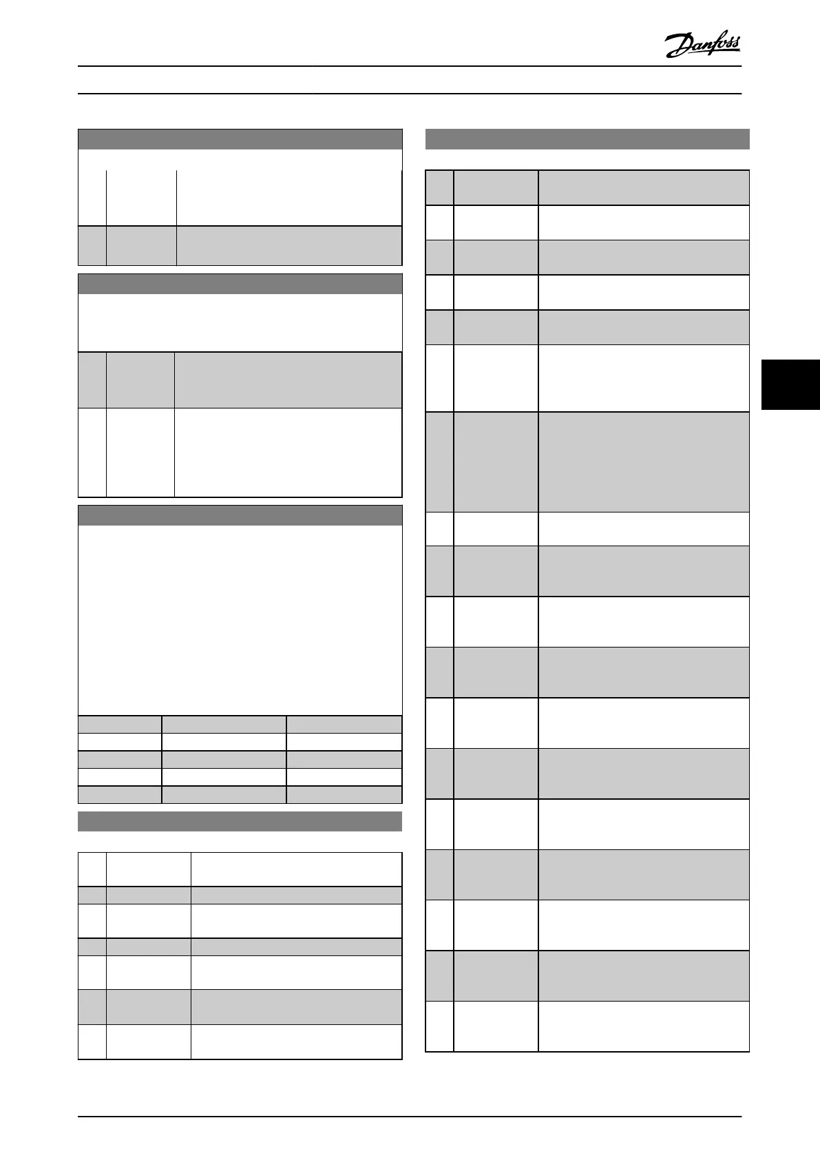
8-05 End-of-Timeout Function
Option: Function:
until 8-06 Reset Control Timeout toggles. Then
the frequency converter resumes its original
set-up.
[1] * Resume set-
up
Resumes the set-up active prior to the time-
out.
8-06 Reset Control Word Timeout
This parameter is active only when Hold set-up [0] has been
selected in 8-05 End-of-Timeout Function.
Option: Function:
[0] * Do not reset
Retains the set-up specified in 8-04 Control
Word Timeout Function, following a control
word time-out.
[1] Do reset Returns the frequency converter to the
original set-up following a control word time-
out. The frequency converter performs the
reset and then immediately reverts to the Do
not reset [0] setting
8-10 Control Word Profile
Select the interpretation of the control and status words
corresponding to the installed fieldbus. Only the selections valid
for the fieldbus installed in slot A will be visible in the LCP
display.
For guidelines in selection of FC profile [0] and PROFIdrive profile
[1] please refer to the Serial communication via RS 485 Interface
section.
For additional guidelines in the selection of PROFIdrive profile [1],
ODVA [5] and CANopen DSP 402 [7], please refer to the Operating
Instructions for the installed fieldbus.
Option: Function:
[0] * FC profile
[1] PROFIdrive profile
[5] ODVA
[7] CANopen DSP 402
[8] MCO
8-13 Configurable Status Word STW
Option: Function:
This parameter enables configuration of
bits 12 – 15 in the status word.
[0] No function
[1] * Profile Default Function corresponds to the profile
default selected in 8-10 Control Profile.
[2] Alarm 68 Only Only set in case of an Alarm 68.
[3] Trip excl Alarm
68
Set in case of a trip, except if the trip is
executed by an Alarm 68.
[10] T18 DI status. The bit indicates the status of terminal
18
*1
.
[11] T19 DI status. The bit indicates the status of terminal
19
*1
.
8-13 Configurable Status Word STW
Option: Function:
[12] T27 DI status. The bit indicates the status of terminal
27
*1
.
[13] T29 DI status. The bit indicates the status of terminal
29
*1
.
[14] T32 DI status. The bit indicates the status of terminal
32
*1
.
[15] T33 DI status. The bit indicates the status of terminal
33
*1
.
[16] T37 DI status The bit indicates the status of terminal
37
*2
.
[21] Thermal
warning
The thermal warning turns on when the
temperature exceeds the limit in the
motor, the frequency converter, the brake
resistor, or the thermistor..
[30] Brake fault
(IGBT)
Output is Logic ‘1’ when the brake IGBT is
short-circuited. Use this function to
protect the frequency converter if there is
a fault on the brake modules. Use the
output/relay to cut out the main voltage
from the frequency converter.
[40] Out of ref
range
[60] Comparator 0 See par. group 13-1*. If Comparator 0 is
evaluated as TRUE, the output will go
high. Otherwise, it will be low.
[61] Comparator 1 See par. group 13-1*. If Comparator 1 is
evaluated as TRUE, the output will go
high. Otherwise, it will be low.
[62] Comparator 2 See par. group 13-1*. If Comparator 2 is
evaluated as TRUE, the output will go
high. Otherwise, it will be low.
[63] Comparator 3 See par. group 13-1*. If Comparator 3 is
evaluated as TRUE, the output will go
high. Otherwise, it will be low.
[64] Comparator 4 See par. group 13-1*. If Comparator 4 is
evaluated as TRUE, the output will go
high. Otherwise, it will be low.
[65] Comparator 5 See par. group 13-1*. If Comparator 5 is
evaluated as TRUE, the output will go
high. Otherwise, it will be low.
[70] Logic Rule 0 See par. group 13-4*. If Logic Rule 0 is
evaluated as TRUE, the output will go
high. Otherwise, it will be low.
[71] Logic Rule 1 See par. group 13-4*. If Logic Rule 1 is
evaluated as TRUE, the output will go
high. Otherwise, it will be low.
[72] Logic Rule 2 See par. group 13-4*. If Logic Rule 2 is
evaluated as TRUE, the output will go
high. Otherwise, it will be low.
[73] Logic Rule 3 See par. group 13-4*. If Logic Rule 3 is
evaluated as TRUE, the output will go
high. Otherwise, it will be low.
Parameters MCA 121 EtherNet/IP
MG.90.J3.02 - VLT
®
is a registered Danfoss trademark 29
6
6

 Loading...


