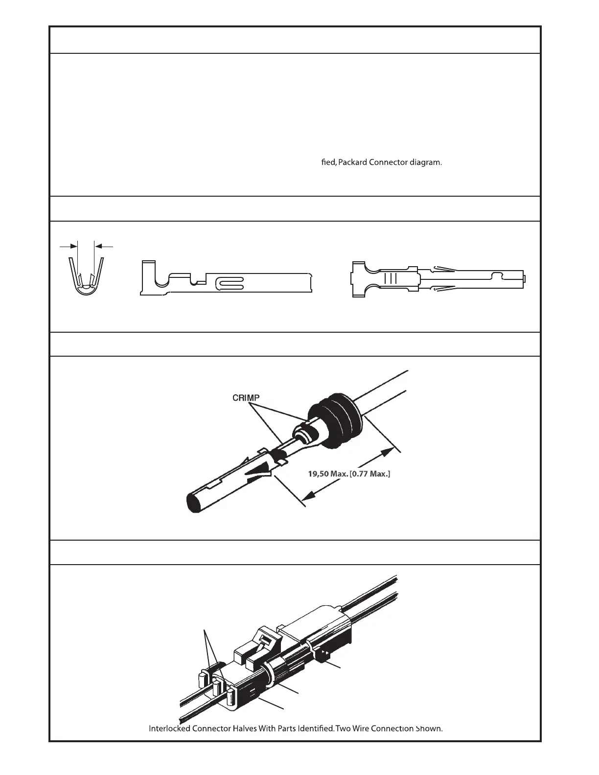
5. The distance from the back of the tangs to the furthest rib
may not exceed 19.5 millimeters. See Distance, Packard
Connector diagram.
6. Manually insert the assembled wires into the back end
(large hole) of the plastic housing. Push until the wire de-
tents with an audible click, then pull back slightly to ensure
proper seating. (Observe the proper phasing of the wires
when installing: Black wire to “A” hole, Red to “B”, Black to
“C” and Red to “D”.) Terminals may be removed from the
connector bodies with a Packard 12014012 removal tool.
WIRING ( continued)
7. Swing the holder down into the detented position to trap
the wires in the housing. The third rib should be sealed into
the housing.
8. Plug the shroud connector from the valve into the tower
connector just constructed. They are sealed with a double
(or quadruple) plug seal over the double (or quadruple)
barrel of the tower assembly. The two connector halves
should detent into each other. See Connector Parts Identi-
1078A
Distance From Tang to Third Rib of Packard Connector.
1077A
DIMENSION A.
DIS TANCE, PACKARD CONNEC TOR
CONNEC TOR PARTS IDENTIFIE D, PACKARD CONNEC TOR
DIMENSION A
1123
Dimension A For Selecting Correct Terminal.
CABLE
SEALS
SIDE "B"
RED
BLACK
SHROUD
CONNECTOR
SIDE "A"
DOUBLE-PLUG SEAL
TOWER CONNECTOR
© Danfoss, 2013
K07116 • Rev AB • September 2013
10
 Loading...