MOUNTING THE NEW HARDWARE
1. Recheck the series number on the control feedback link to
ensure that it is compatible with the pump. If the control is
an MCV104X9XX (i.e., control less linkage assembly), follow
the procedure outlined below to install the linkage. See
Parts Location diagram.
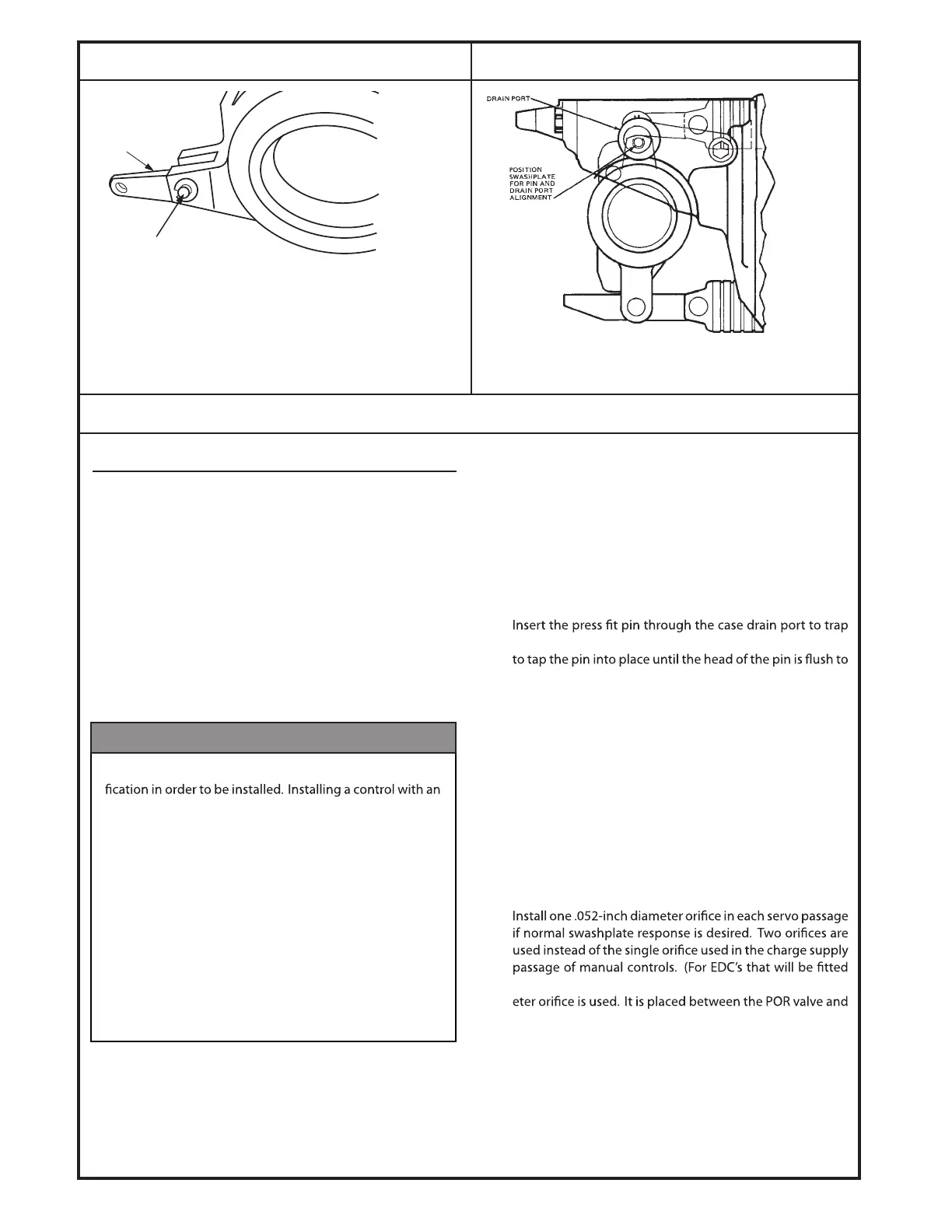
A. Unscrew the bushing, using care not to damage its
O-ring. See Swashplate Location diagram.
B. Install the new linkage assembly shaft through the
swashplate feedback shaft hole. Place the ball in the
crosslink ball cavity.
PIN CONNECTION
SWASHPLATE LOCATION
C. Lubricate the shaft O-ring and replace the bushing
over the shaft. Torque to the body (10 - 15 foot pounds)
so that the feedback shaft extends through the bush-
ing.
D. Install the retaining ring in the groove on the shaft.
2. Align one end of the replacement swashplate drag link with
the holes in the swashplate link arms.
3.
the drag link in the swashplate clevis. It will be necessary
the clevis.
4. Install the retaining ring by forcing it onto the tapered end
.tfahs nip eht no evoorg eht otni skcol ti litnu nip eht fo
Again, use caution not to drop any components into the
pump housing.
5. Install the supplied spacer between the control and the
pump housing. If the pump is a 20 Series, the spacer is
one-quarter inch thick; if it is a 26 Series, the spacer is 1 1/2
inch thick. Other series’ do not require a spacer. One gasket
and 3 O-rings must be installed on the under side of the
spacer.
6.
with the pressure override valve, only one .042-inch diam-
the EDC.) Install 3 O-rings and a gasket. If a spacer is used,
there should now be 6 O-rings and 2 gaskets in place.
7. Engage the pin on the control in the drag link and swing
the control into place against the pump housing. The drag
.etalphsaws eht fo edis kcolb rednilyc eht no eb dluohs knil
Install the seven mounting screws and tighten to 10-11 foot
pounds of torque.
Pin Connection to Swashplate.
Shown Disassembled for Clarity.
Location of Swashplate Assembly in Pump Housing.
1125C
1126B
MOUNTING (continued)
DRAG LINK
REMOVE "E" RINGS,
PIN AMD DRAG LINK
The control and feedback link must have the proper identi-
improper control feedback link can result in a control failure
which can cause the pump swashplate to move to full angle
and remain there independent of signal input.
Do not attempt to install an EDC on a pump for which it
was not originally designed without changing the link-and-
ball assembly. Merely changing the swashplate drag link
is inadequate. See Ordering Information for the necessary
link-and-ball assembly number. In no case should a valve
originally built for a Series 2X pump be used on a Series
3X pump.
WARNING
© Danfoss, 2013
K07116 • Rev AB • September 2013
13
 Loading...