TECHNICAL DATA
ELECTRICAL
NOMINAL START CURRENT
± 11 mA (single coil)
± 16 mA (using one of the dual coils)
± 8 mA (using the dual coils in series)
± 16 mA (using the dual coils in parallel)
± 6.25 mA (low current models)
NOMINAL FULL STROKE CURRENT
(See Current vs. Swashplate Angle and Wiring Schemes)
85 ± 12 mA (single coil)
125 ± 18 mA (using one of the dual coils)
62 ± 9 mA (using the dual coils in series)
125 ± 18 mA (using the dual coils in parallel)
18 ± 1.5 mA (low current models)
Current tolerances include ± 5 mA for single coil and ±
pump series’. For sizing drive sources, use 100 mA in compu-
tations for single coil EDC’s.
COIL RESISTANCE @ 24° C (76° F)
23 ohms (single coil)
19.5 ohms (A, B Terminals),
15.5 ohms (C, D Terminals) (dual coil)
650 ohms (low current models)
COIL RESISTANCE @ 104° C (220° F)
29 ohms (single coil)
24.7 ohms (A, B Terminals),
19.7 ohms (C, D Terminals) (dual coil)
800 ohms (low current models)
COIL INDUCTANCE
.14 henries (single coil)
.062 henries (A, B Terminals),
.047 henries (C, D Terminals) (dual coil)
MAXIMUM CONTINUOUS VOLTAGE @ 93.3° C(200° F)
• 7.5 Vdc for single coil models with the exceptionof those
low current models
• 14 Vdc for dual coil models in series
• 7.5 Vdc for dual coil models when only one coil or both coils
in parallel are used
• 24 Vdc for low curent models.
The EDC is designed to be controlled from a dc current source or
voltage source. Pulse width modulation (PWM) is not required.
But if a PWM signal is used, avoid a carrier frequency <200 Hz.
Do
not
use a pulse current of more than 120% of that required
for full output.
HYDRAULIC
OIL VISCOSITY
40 - 6000 SSU
OIL TEMPERATURE
- 40° C (- 40° F) minimum
+ 104° C (+220° F) maximum continuous
+ 116° C (+240° F) maximum intermittent
AMBIENT OPERATING TEMPERATURE
- 40° to 93° C (- 40° to 200° F)
SINGLE COIL 85 MA
WITH 2.0 VDC
INPUT AT FULL STROKE.
B
USING ONE OF THE TWO DUAL COILS
,
125 MA WITH 1.9 VDC (C, D COIL) OR
2.4 VDC (A, B COIL)
INPUT AT FULL STROKE.
B
+C
D
DUAL COILS IN SERIES,
62 MA WITH 2.2 VDC
INPUT AT FULL STROKE.
+
B
C
D
A
DUAL COILS IN PARALLEL,
125 MA WITH 1.1 VDC
INPUT AT FULL STROKE.
+
B
C
D
A
B
SINGLE COIL 20 MA
WITH 15 VDC
INPUT AT FULL STROKE.
(LOW CURRENT MODEL)
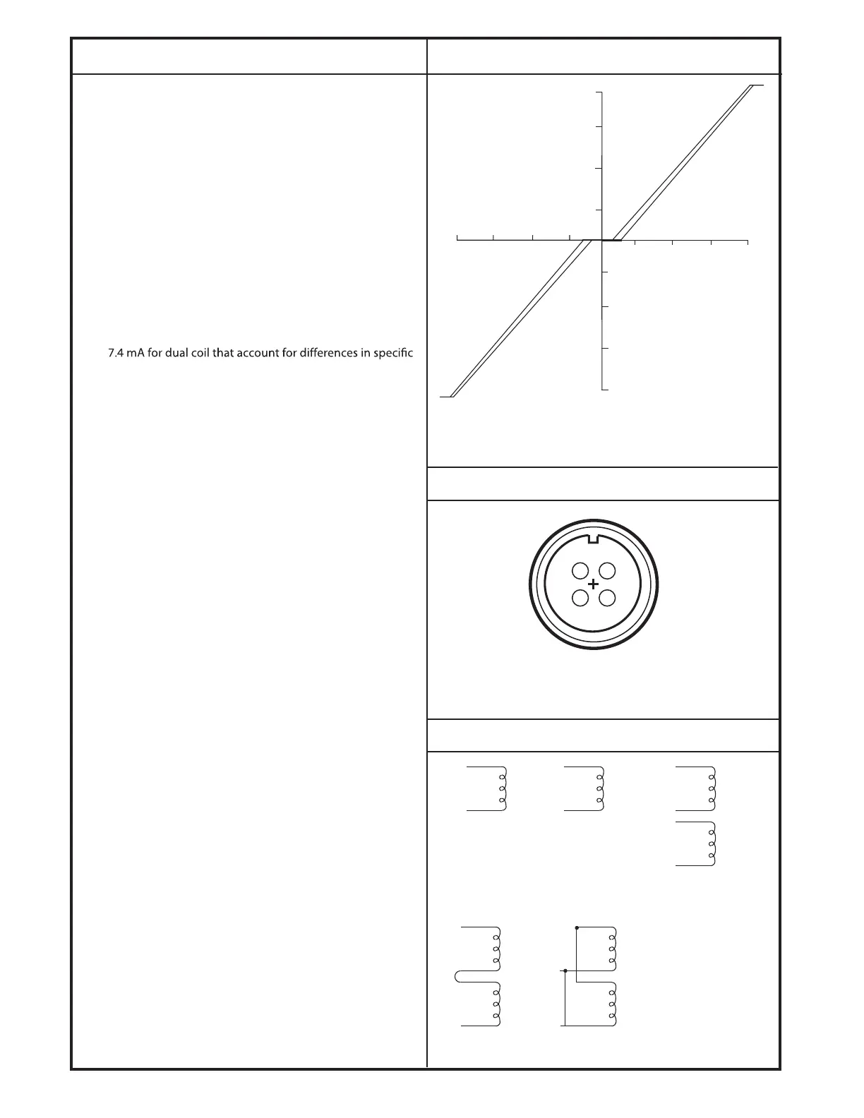
CURRENT VS. SWASHPLATE ANGLE
Current Vs. Swashplate Angle for the MCV104A.
Single-Coil Load Pressure is 3000 PSI and Current Input is 0.01
Hz.
1141
15∞
10∞
5∞
5∞
10∞
15∞
80 mA 60 mA 40 mA 20 mA
20 mA 40 mA 60 mA 80 mA
18∞
18∞
SWASHPLATE ANGLE (DEGREES)
INPUT CURRENT (MA)
1300
WIRING SCHEMES
CONNECTION DIAGRAM
Pin Orientation of 4-pin, 90° MS Mating Connector. Part
No. MS3108E-14S-2S (Sauer-Danfoss Kit No. K08106).
1276
D
C
A
B
700
Ω
24
Ω
19.5
Ω
15.5
Ω
35 Ω
(TOTAL
RESISTANCE)
9 Ω
(TOTAL
RESISTANCE)
© Danfoss, 2013
K07116 • Rev AB • September 2013
5
 Loading...