© Danfoss | Climate Solutions | 2022.08
AN41473467835501-000102 | 3
Initial conguration
The rst time the unit receives the power supply, it will enter into ASSISTANT mode. The display will show
the message ashing with 0.
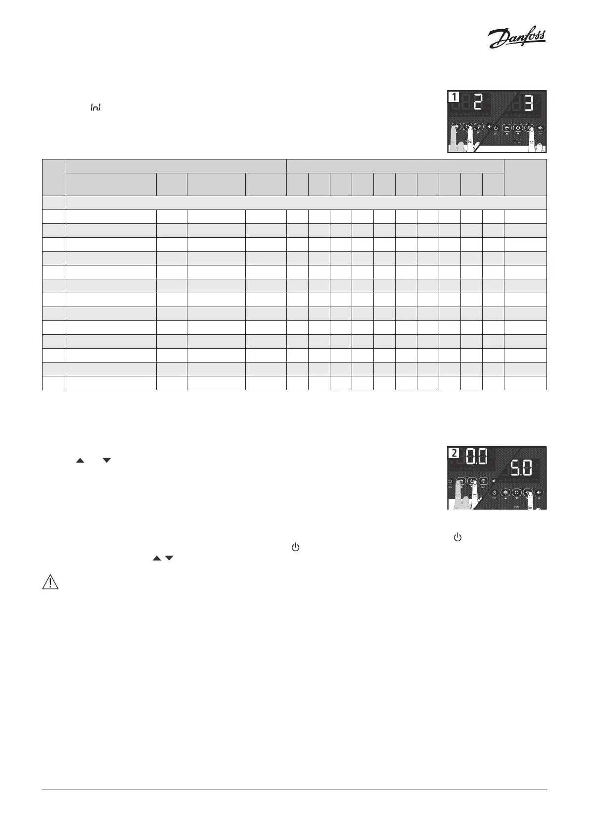
Step 1:
Select the most suitable InI option based on the type of installation to be carried out and press SET. The
available options will be shown in the following table:
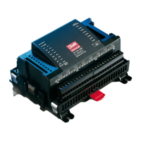
Step 2:
Use keys and to enter the desired Temperature Set Point value and press SET. The wizard has nished.
The unit will begin to regulate the temperature.
If this is not the rst time you use the wizard, after completing the last step the display will show the
message dFp (default parameters). You may choose between two options:
0: Only changing the parameters which aect the wizard. The other parameters will remain the same.
1: All parameters return to their factory setting except those which have been modied by the wizard.
Important: The wizard will not reactivate. To enter the wizard mode, initiate Stand-by mode by pressing the key for 3 seconds and
wait until the unit completely halts the temperature regulation (the indicator will light up permanently) and press the following keys in
sequence one after the other, , , SET.
Warning: If the pump down function is active, a certain amount of time may elapse between starting the stand-by function and the
controller stopping.
Note: If options 2, 5, 7, 9 or 12 are chosen, check the conguration of parameter I11 according to the pressure switch type used. (See
diagram included with the device).
* o00=2 in AK-RC 204B, o00=0 in AK-RC 205C
InI
Type of installation Parameters
Diagram
to be
used
Cold regulation
Pump
Down
Defrost
Evap.
fans
Pd
o00 I00 I10 I11 I20 I21 d1 d7 F3
0 Demo Mode: it displays the temperature but does not regulate the temperature or activate relays
1 Solenoid No Electric Yes 0 * 2 0 0 0 0 20 0 0 A
2 Solenoid + compressor Yes Electric Yes 1 1 2 7 1 0 0 20 0 0 B
3 Solenoid + compressor No Electric Yes 0 1 2 0 0 0 0 20 0 0 B
4 Solenoid No Air Yes 0 * 1 0 0 0 0 20 1 1 A
5 Solenoid + compressor Yes Air Yes 1 1 1 7 1 0 0 20 1 1 B
6 Solenoid + compressor No Air Yes 0 1 1 0 0 0 0 20 1 1 B
7 Solenoid + compressor Yes Hot gas Yes 1 1 2 7 1 9 1 5 2 0 C
8 Solenoid + compressor No Hot gas Yes 0 1 2 0 0 9 1 5 2 0 C
9 Solenoid + compressor Yes Reversed cycle Yes 1 1 2 7 1 0 0 5 3 0 D
10 Solenoid + compressor No Reversed cycle Yes 0 1 2 0 0 0 0 5 3 0 D
11 Solenoid No Static No 0 * 1 0 0 0 0 20 1 - A
12 Solenoid + compressor Yes Static No 1 1 1 7 1 0 0 20 1 - B
13 Solenoid + compressor No Static No 0 1 1 0 0 0 0 20 1 - B