11BC08728642552802-001001
Manual
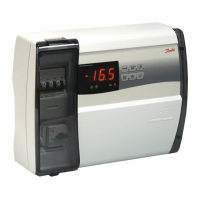
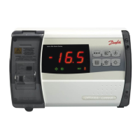
• In case of “malfunctions” 3 small LED
symbols will flash on the controller’s screen.
Acknowledge with a short press on upper
button. Here some examples below …
A2 Low Suction Pressure Alarm
A17
Safety Input Alarm (DI3: High condensing
/ low suction pressure)
A96 Discharge Gas Temperature High
A97
Digital Input Alarm (DI2: Frequency
converter alarm)
E20 Condensing Pressure Transmitter Error
E31 Ambient Temperature Sensor Error
E32 Discharge Temperature Sensor Error
E33 Suction Gas Temperature Sensor Error
E39 Evaporating Pressure Transmitter Error
Alarm and Error Messages
Repair
Fixed speed units:
See wiring diagrams on p. 4.
• Disconnect the condensing unit from power supply (turn hardware main switch off)
• Remove wire from controller terminal 22 (safety input DI3) and terminal 25 (room thermostat DI1)
and put them together
• Remove wire from controller terminal 24 (room thermostat DI1) and terminal 11 (compressor
supply) and put them together
• Remove wire 6* and connect it with terminal bridge for wire 11 and 24.
• Remove wire from terminal 14 (crankcase heater) and connect it to compressor contactor K2
terminal 22
• Remove wire from controller terminal 12 (supply crankcase heater), extend this wire
approximately 40cm and connect it to compressor contactor K2 terminal 21
• Pay attention: Remove the big terminal block from the controller or remove the complete controller
• Connect the condensing unit back to power supply (turn hardware main switch on)
Variable speed units:
See wiring diagrams on p. 5.
• Disconnect the condensing unit from power supply (turn hardware main switch off)
• Remove wire from controller terminal 22 (safety input) and terminal 6* (fan) and put them
together
• Remove wire from controller terminal 10 (compressor relay) and terminal 24 (room thermostat)
and put them together
• Remove wire from controller terminal 11 (compressor relay) and terminal 25 (room thermostat)
and put them together
• Remove wire from Inverter terminal 50 and connect to Potentiometer terminal 3
• Remove wire from Inverter terminal 53 and connect to Potentiometer terminal 2
• Remove wire from Inverter terminal 55 and connect to Potentiometer terminal 1
• Remove wire from terminal 14 (crankcase heater) and connect it to compressor contactor K1
terminal 22
• Remove wire from controller terminal 12 (supply crankcase heater), extend this wire
approximately 40cm and connect it to compressor contactor K1 terminal 21
• Pay attention: Remove the big terminal block from the controller or remove the complete controller
• Connect the condensing unit back to power supply (turn hardware main switch on)
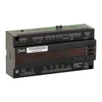
Controller failure
(if the controller fails, there is a
possibility to run the condensing
unit in “manual” mode. Proceed as
follows)
*Option: A fan pressure switch or fan speed controller can be connected in series to wire n°6
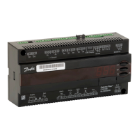
Controller Installation
 Loading...