Instruction Pump instruction PAH / PAHT 2-12.5
36 |
© Danfoss | DHS (im) | 2022.07
1180R9379 | AQ188686503004en-000801 | PAH 2-12.5
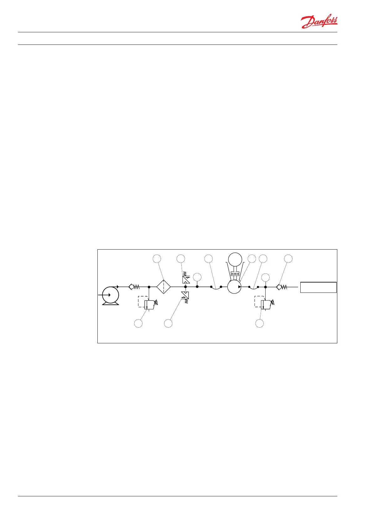
2.2 Open-system design
A Inlet line:
Dimension the inlet line to obtain mini-
mum pressure loss (large ow, minimum
pipe length, minimum number of bends/
connections, and ttings with small
pressure losses).
B Inlet lter:
Install the inlet lter (1) in front of the PAHT
pump (2). Please consult the Danfoss lter
data sheet for guidance on how to select
the right lter.
C Monitoring pressure switch:
Install the monitoring pressure switch (3)
between the lter and the pump inlet. Set
the minimum inlet pressure according to
specications described in item 4, technical
data. The monitoring pressure switch stops
the pump if inlet pressure is lower than the
set minimum pressure.
D Monitoring temperature switch:
Install the monitoring temperature switch
(4) between the lter and the pump, on
either side of the monitoring pressure
switch. Set the temperature value accord-
ing to technical data, item 4. The monitor-
ing temperature switch stops the pump if
inlet temperature is higher than the set
value.
E Hoses:
Always use exible hoses (5) to minimize
vibrations and noise.
F Inlet pressure:
In order to eliminate the risk of cavitation
and other pump damage, pump inlet
pressure must be maintained according to
specications described in item 4, technical
data.
G Non-return valve (6):
Should be installed after the outlet to
prevent pump backspin, which may ruin
the pump.
H Pressure relief valve:
As the Danfoss PAHT pump begins to
create pressure and ow immediately after
start-up regardless of any counter pressure,
a pressure relief valve (7) should be
installed to prevent system damage.
Note: If a non-return valve is mounted in the
inlet line, a low-pressure relief valve is also
required between the non-return valve (8) and
the pump to protect against high-pressure
peaks.
M
2
SYSTEM
1 4 5 5 6
73
PI
PI
8

 Loading...