MG.20.B6.02 – VLT is a registered Danfoss trademark
71
VLT
®
2000 Series
Section 1 Section 2 Section 3
✭ = Factory setting. Text in ( ) = Display text. The figures in [ ] are used in bus communication.
Description of parameters
310 Trip delay at current limit (TRIP DLY@C.LIM)
Value:
0 - 60 sec.
✭ Infinite at 61
Function:
Using this parameter you can record how long the
current limit may be active before trip.
Description:
Record the delay time.
Warning:If you choose Infinite, and your load
is between 105% and 160%, trip may occur
after a given interval.
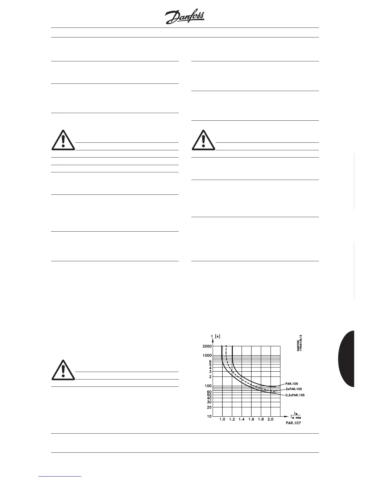
315 Motor thermal protection (MOTOR THERMAL)
308 DC brake voltage (DC-BRK VOLTAGE)
Value:
0 - 50 V ✭ 10 V
Function:
Using this parameter you can record the DC brake
voltage for the motor.
Description:
The size of the voltage depends on the motor size.
The bigger the motor the lower the DC brake voltage.
Warning: At frequent DC-braking the DC
brake voltage should not be too high.
This is to avoid motor overload. The DC brake
voltage must be > 0 to activate DCbraking.
309 Reset mode (RESET MODE)
Value:
✭ Manual reset (MANUAL) [0]
Auto reset 1 (AUTORESET 1) [1]
Auto reset 5 (AUTORESET 5) [5]
Function:
Using this parameter you can choose how you want
to reset an alarm.
Description:
If you choose Manual reset you must reset the VLT
frequency converter via the keyboard or via terminals
19, 27 or 29. The display shows TRIP.
If you choose Auto reset 1 the VLT frequency conver-
ter will automatically try to reset once after alarm. The
display shows AUTO START
As long as the display shows AUTOSTART the unit
will try to reset every 20 minutes.
If you choose Auto reset 5 the VLT will automatically
try to reset 5 times after alarm. The display shows
AUTO START.
Warning: The motor may start without
warning, if Auto reset selected.
Value:
✭ Off (PROTECT OFF) [0]
Only warning (ONLY WARNING) [1]
Trip (TRIP) [2]
Function:
The VLT frequency converter calculates if the motor
temperature exceeds the limits allowed. The
calculation is based on 1.16 x rated motor current at
rated fre-quency (parameter 107).
Description:
Choose Off if you do not want any display indication
of either warning or trip.
Choose Only warning if you want display indication for
motor overloaded.
You can also program the frequency converter to give
a warning signal via the signal outputs (parameters
408 and 409).
Choose Trip if you want warning and trip to be
displayed.
■
■
■
■
 Loading...