ETR trip 2 (ETR TRIP 2) [6]
ETR warning 3 (ETR WARNING 3) [7]
ETR trip 3 (ETR TRIP 3) [8]
ETR warning 4 (ETR WARNING 4) [9]
ETR trip 4 (ETR TRIP 4) [10]
Function:
The frequency converter can monitor the motor tem-
perature in two different ways:
-
Via a PTC thermistor that is mounted on the
motor. The thermistor is connected between
terminal 50 (+10V) and one of the digital input
terminals 18, 19, 27 or 29. See parameter
300 Digital inputs.
-
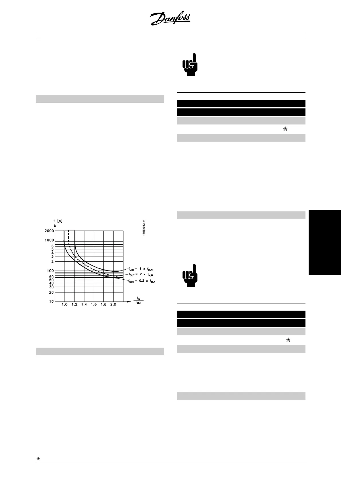
Thermal load calculation (ETR - Electronic
Thermal Relay), based on present load and
time. This is compared with the rated motor
current I
M,N
and rated motor frequency f
M,N
.
The calculations take into account the need
for lower loading at low speeds due to the
motor's internal ventilation being reduced.
ETR functions 1-4 do not begin to calculate the load
until you switch to the Setup in which they have been
selected. This means that you can use the ETR func-
tion even when changing between two or more motors.
Description of choice:
Select No protection [0] if you do not want a warning
or trip when a motor is overloaded.
Select Thermistor warning [1] if you want a warning
when the connected thermistor becomes too hot.
Select Thermistor trip [2] if you want a trip when the
connected thermistor becomes too hot.
Select ETR warning 1-4 if you want a warning when the
motor is overloaded according to the calculations. You
can also programme the frequency converter to give a
warning signal via one of the digital outputs. Select
ETR Trip 1-4 if you want a trip when the motor is over-
loaded according to the calculations.
NB!
This function cannot protect the individual
motors in the case of motors linked in par-
allel.
130 Start frequency
(Start frequency)
Value:
0.0 - 10.0 Hz
0.0 Hz
Function:
The start frequency is active for the time set in param-
eter 120 Start delay, after a start command. The output
frequency will 'jump' to the next preset frequency. Cer-
tain motors, such as conical anchor motors, need an
extra voltage/start frequency (boost) at start to disen-
gage the mechanical brake. To achieve this parame-
ters 130 Start frequency and 131 Initial voltage are
used.
Description of choice:
Set the required start frequency. It is a precondition
that parameter 121 Start function, is set to Start fre-
quency/voltage clockwise [3] or Start frequency voltage
in reference direction [4] and that in parameter 120 Start
delay a time is set and a reference signal is present.
NB!
If parameter 123 is set higher than param-
eter 130, the start delay function (param-
eter 120 and 121) will be skipped.
131 Initial voltage
(INITIAL VOLTAGE)
Value:
0.0 - 200.0 V
0.0 V
Function:
Initial voltage is active for the time set in parameter 120
Start delay , after a start command. This parameter can
be used for example for lifting/dropping applications
(conical anchor motors).
Description of choice:
Set the required voltage necessary to cut out the me-
chanical brake. It is assumed that parameter 121 Start
function, is set to Start frequency/voltage clockwise [3]
or Start frequency/voltage in reference direction [4] and
= factory setting, () = display text, [] = value for use in communication via serial communication port
MG.27.E2.02 - VLT is a registered Danfoss trademark 73
Programming
 Loading...


