The jog ramp time starts if a jog-signal is given via the
LCP control panel, one of the digital inputs or the serial
communication port.
Description of choice:
Set the required ramp time.
212 Quick-stop ramp-down time
(Q STOP RAMP TIME)
Value:
0.02 - 3600.00 sec.
3.00 sec (VLT 2803-2875)
10.00 sec (VLT 2880-2882)
Function:
The quick-stop ramp-down time is the deceleration
time from the rated motor frequency to 0 Hz, provided
no overvoltage arises in the inverter because of gen-
erating operation of the motor, or if the generated
current exceeds the current limit in parameter 221
Current limit I
LIM
. Quick-stop is activated via one of the
digital inputs or the serial communication.
Description of choice:
Set the required ramp-down time.
213 Jog frequency
(Jog frequency)
Value:
0.0 - Par. 202 Output frequency high
limit, f
MAX
10.0 Hz
Function:
Jog frequency f
JOG
means a fixed output frequency
that the frequency converter supplies to the motor
when the Jog function is activated. Jog can be activa-
ted via the digital inputs, serial communication or via
the LCP control panel, on the condition that this is ac-
tive in parameter 015 Local jog.
Description of choice:
Set the required frequency.
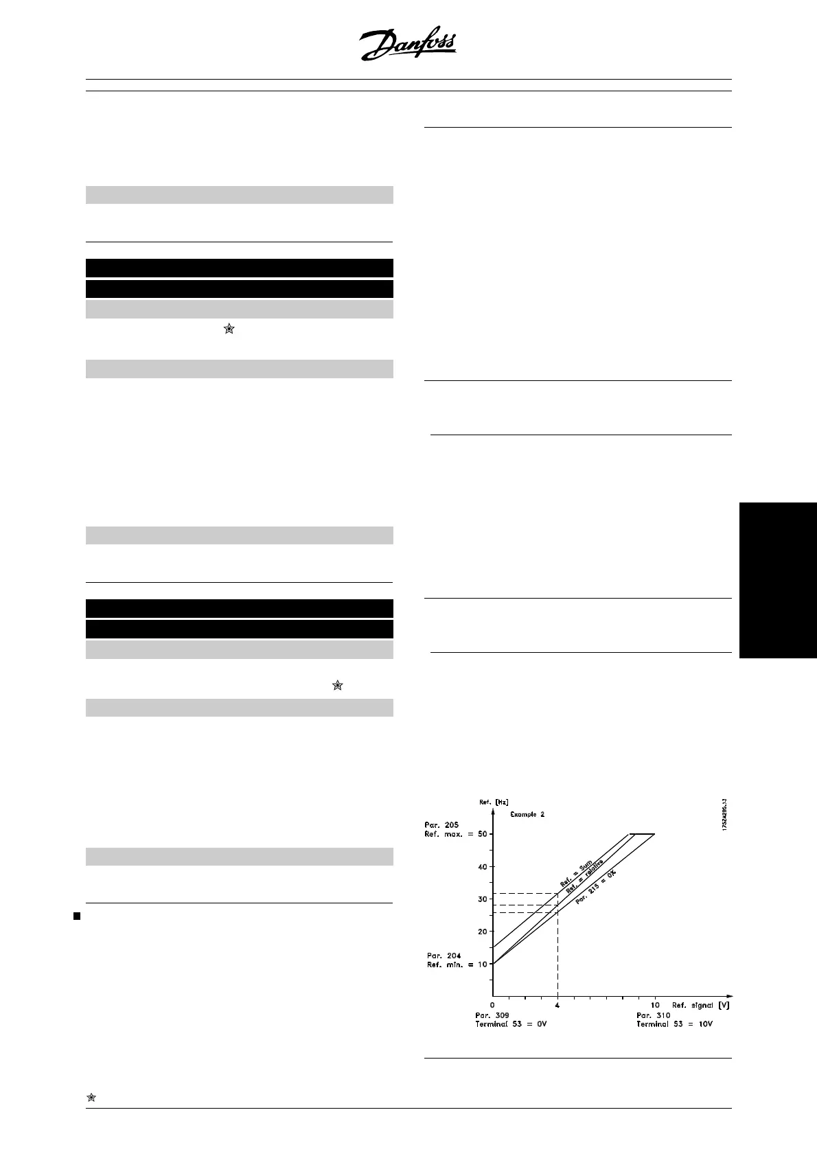
Reference function
The example shows how the resulting reference is cal-
culated when Preset references is used together with
Sum and Relative in parameter 214 Reference func-
tion. The formula for the calculation of the resulting
reference can be seen in the section entitled All about
the VLT 2800. See also the drawing in Handling of ref-
erences.
The following parameters are preset:
Par. 204 Minimum reference
10 Hz
Par. 205 Maximum reference
50 Hz
Par. 215 Preset reference
15 %
Par. 308 Term. 53, Analogue input
Reference
Par. 309 Term. 53, min. scaling
0 V
Par. 310 Term. 53, max. scaling
10 V
When parameter 214 Reference function is set to
Sum [0] one of the preset Preset references(par.
215-218) is added to the external references as a per-
centage of the reference range. If terminal 53 is ap-
plied an analogue input voltage of 4 Volt will be the
resulting reference:
Par. 214 Reference function = Sum [0]:
Par. 204 Minimum reference
10.0 Hz
Reference contribution at 4 Volt 16.0 Hz
Par. 215 Preset reference
6.0 Hz
Resulting reference 32.0 Hz
When parameter 214 Reference function is set to Rel-
ative [1] the defined Preset references (par. 215-218)
are added as a percentage of the total of the present
external references. If terminal 53 is applied to an an-
alogue input voltage of 4 Volt the resulting reference
will be:
Par. 214 Reference function = Relative [1]:
Par. 204 Minimum reference
10.0 Hz
Reference effect at 4 Volt 16.0 Hz
Par. 215 Preset reference
2.4 Hz
Resulting reference 28.4 Hz
The graph shows the resulting reference in relation to
the external reference, which varies from 0-10 Volt.
Parameter 214 Reference function is programmed to
Sum [0] and Relative [1] respectively. Also shown is a
graph in which parameter 215 Preset reference 1 is
programmed to 0 %.
= factory setting, () = display text, [] = value for use in communication via serial communication port
MG.27.E2.02 - VLT is a registered Danfoss trademark 81
Programming
 Loading...


