Do you have a question about the Danfoss VLT 2881 and is the answer not in the manual?
General safety warning related to the unit's operation.
Guidelines for physical installation and mounting of the frequency converter.
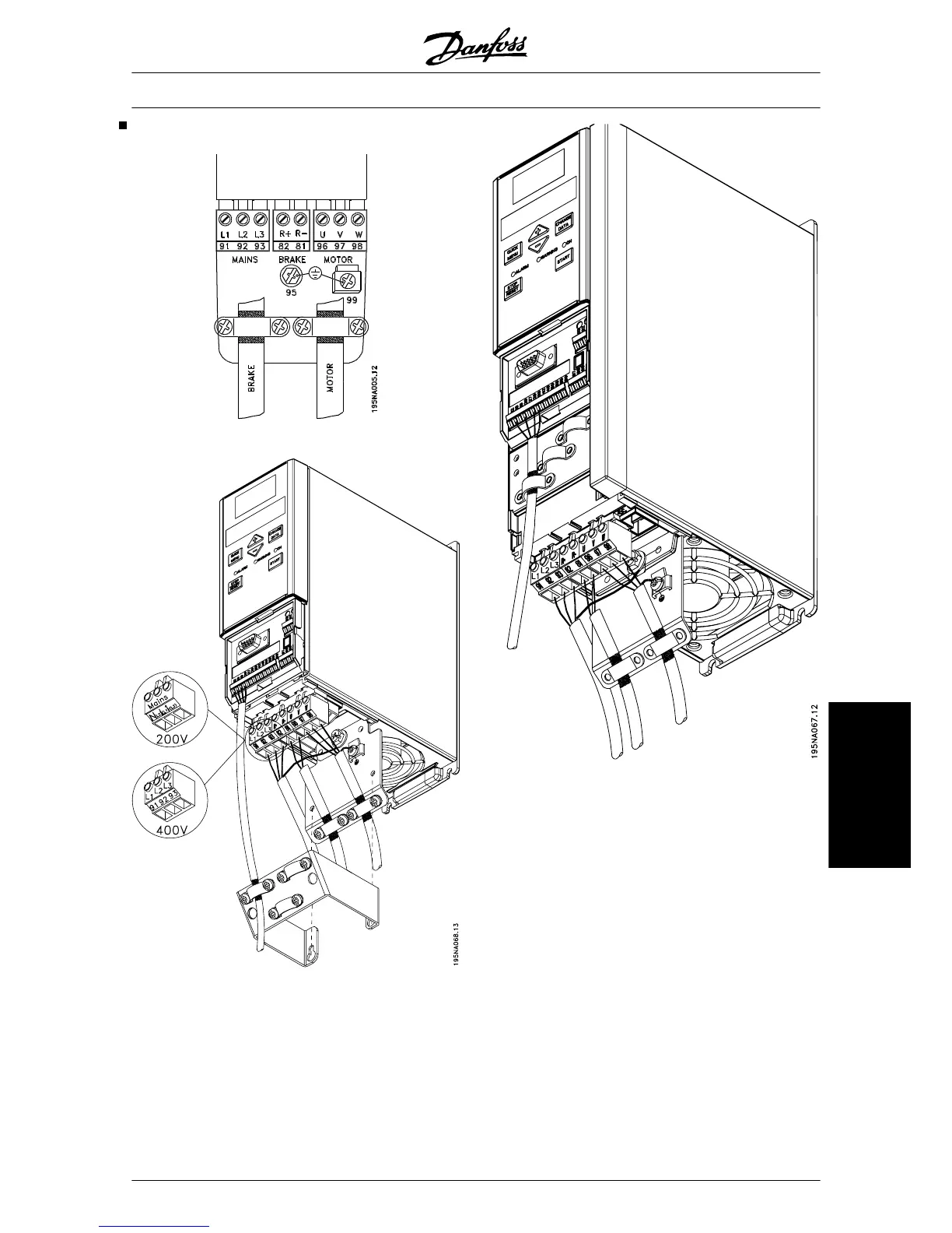
Instructions for connecting power supply to the frequency converter.
Procedures for connecting control cables to the frequency converter.
Initial steps for programming basic motor parameters.
Alerts users to the dangers of high voltage when the unit is connected to mains.
Outlines essential safety rules for handling and installation of the unit.
Specific warnings about preventing accidental motor starts.
Description of the function and operation of control panel keys.
Selecting the frequency converter's configuration for the application.
Defining the U/f ratio adaptation to the load's torque characteristic.
Setting the minimum motor frequency limit for operation.
Setting the maximum motor frequency limit for operation.
Mapping functions to digital input terminals for control.
Selecting the brake function type: resistor, AC brake, or load sharing.
Configuring manual or automatic reset after a trip.
Setting the time before disconnection upon reaching current limit.
Feature to stop the pump in case of dry run, protecting motor and pump.
Drawings showing the physical dimensions of the frequency converter units.
Requirements for mounting the frequency converter for proper cooling.
General guidelines for safe and compliant electrical installation.
Key points for ensuring electromagnetic compatibility in installation.
Precautions for installing the converter in environments with liquids, particles, or gases.
Adjustments needed for rated output current at high ambient temperatures.
Protection against motor overload using electronic thermal relay.
Monitoring power module temperature to prevent overheating.
Protection against short-circuits on motor output terminals.
How the converter protects against missing mains phases.
Monitoring intermediate circuit voltage for over/under voltage protection.
Protection against earth faults on motor output terminals.
Selecting motor direction and maximum output frequency.
Setting the maximum output current to protect the system.