12
MG.60.N1.22 - VLT is a registered Danfoss trademark
VLT
®
5000 / VLT
®
6000 HVAC / VLT
®
8000 AQUA
Installation Instructions
1. Access to
Control
Card
Cassette
• Remove control wiring by unplugging
connector terminals (A).
• Remove grounding clamps (B) by
removing two screws holding each in
place. Save screws for reassembly.
• Loosen two captive screws (C) securing
cassette to chassis.
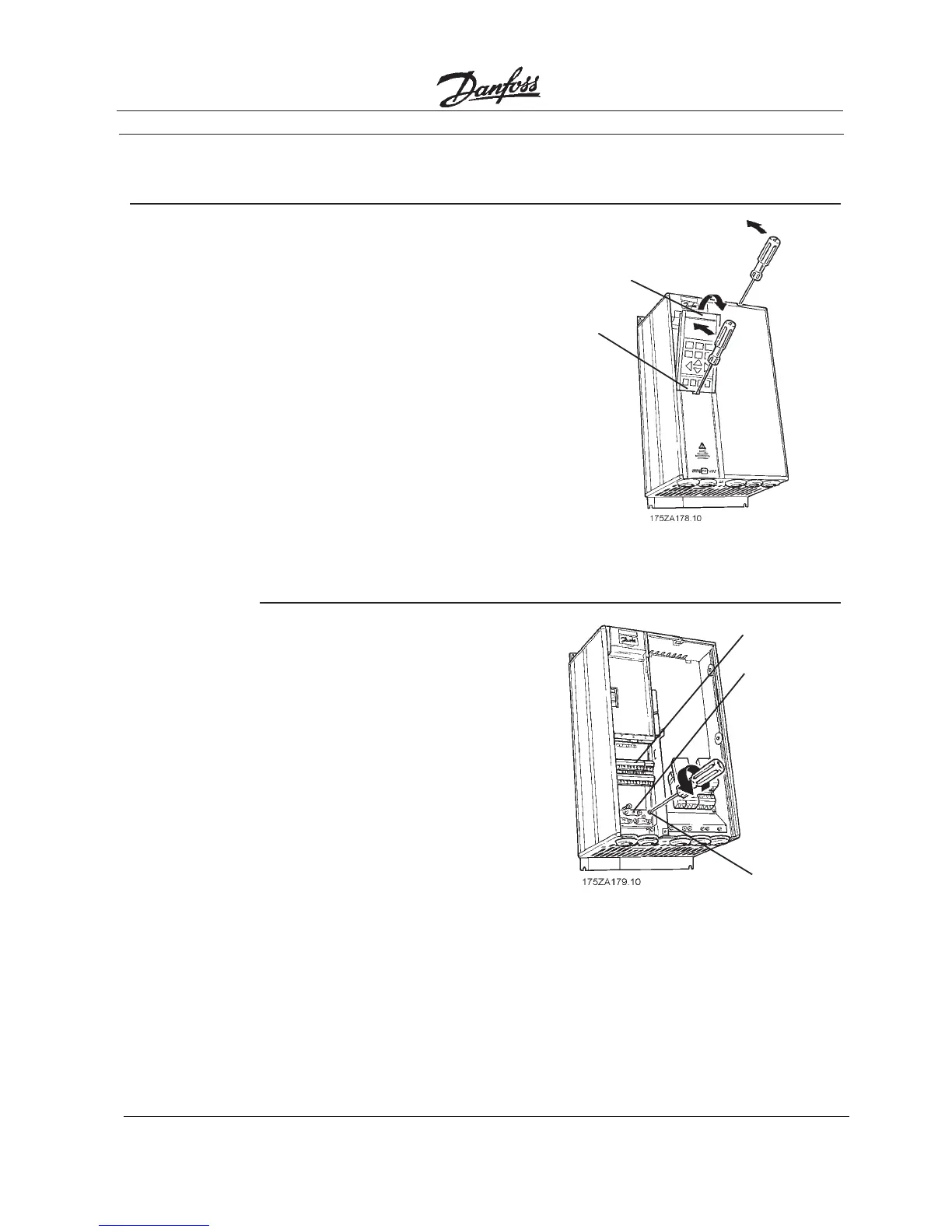
2. Disconnect
Control
Card
Cassette
IP20/NEMA 1 and Bookstyle
• Remove Local Control Panel (LCP) by
pulling out from top of display (A) by
hand. LCP connector on panel back
will disconnect.
• Remove protective cover by gently
prying with a screw driver at notch (B)
and lift cover out of guide pin fittings.
IP54/NEMA 12
• Open front panel of drive by loosening
captive screws and swing open.
• Disconnect Local Control Panel (LCP)
cable from drive control card.
(A)
(B)
(A)
(B)
(C)