14
MG.60.N1.22 - VLT is a registered Danfoss trademark
VLT
®
5000 / VLT
®
6000 HVAC / VLT
®
8000 AQUA
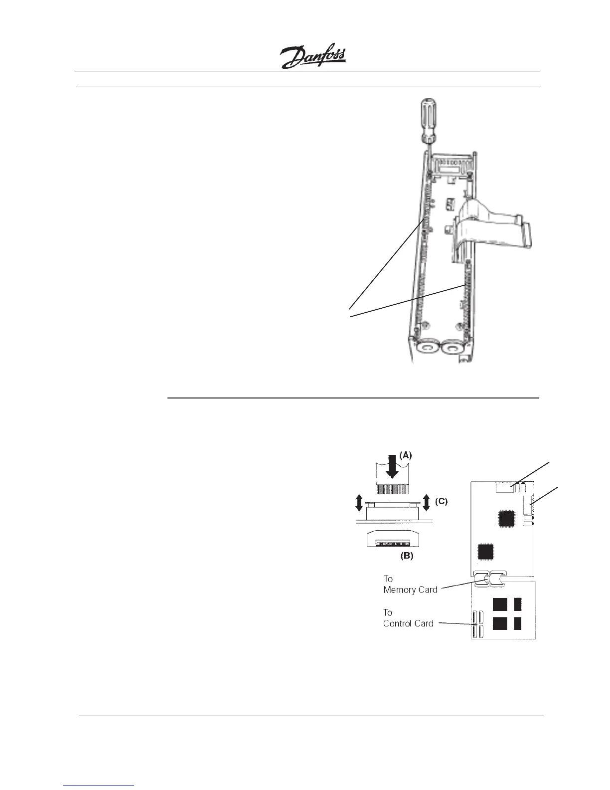
• Align ground strips over screw holes.
Strip with fewest contact points mounts
on cable side of chassis. Tabs on
grounding strips point toward outside
of chassis.
• Replace screws removed in step 4 and
add additional screws and washers
provided, as necessary. Tighten to
0.9 Nm (8 in-lbs) using Torx T-20 screw
driver.
5. Install
Chassis
Ground
Connections
Ground
Strips
• Attach ribbon cables between
LonWorks control card and memory
card.
• Be sure exposed wire portion of ribbon
cable (A) is facing front of socket (B).
Do not remove blue insulation covering
end of ribbon cable.
• Pull up collar (C) of ribbon cable socket,
insert cable and push collar closed.
• Repeat procedure for all ribbon cables.
IP20/NEMA 1 and IP54/NEMA 12
• Remove terminal connector from
terminal block (D) and connect to
terminal block (E) at this time for ease
of access.
6. Install
Ribbon
Cables
between
Option
Cards
(D)
(E)