18
MG.60.N1.22 - VLT is a registered Danfoss trademark
VLT
®
5000 / VLT
®
6000 HVAC / VLT
®
8000 AQUA
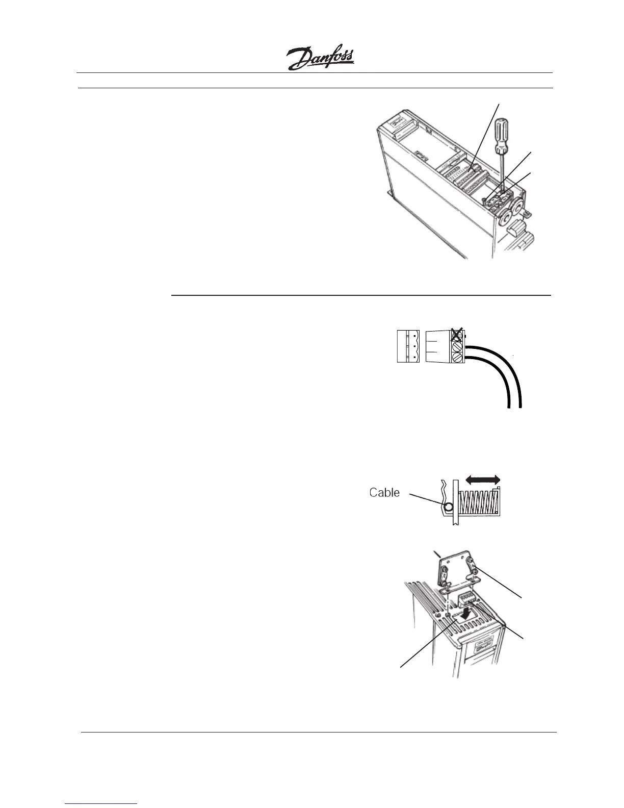
15. Install
Control Card
Cassette
16. Plug in
Terminal
Connector
NOTE
Shielded cable is recommended.
Ground shielded cable at spring
tension clip location or ground at
cable clamp by removing cable
insulation at contact point. Do not
use connector terminal 61.
• Fasten control card cassette by
alternately tightening two captive
screws (A). Tighten to 0.9 Nm (8 in-lbs).
• Route control wires through clamp
fasteners (B) and secure clamps with
two screws.
• Connect control terminals (C) by firmly
pressing them into connector
receptacles.
(A)
(B)
(C)
• Connect signal wire NET A to terminal
79 and NET B to 80 of terminal
connector. (In free topology model,
connections can be reversed.)
IP20/NEMA 1 and IP54/NEMA 12
• Plug network connector into terminal
block at side of control card cassette.
• Insert LonWorks cable between inner
wall of chassis and spring tension clip.
Bookstyle
• Remove knockout from top of drive (A).
• Route control wires through clamp
fasteners (B) on cable plate and secure
clamps with screws. Tighten to 0.9 Nm
(8 in-lbs).
• Secure cable plate to drive with screws
and screw holes provided. Tighten to
0.9 Nm (8 in-lbs).
• Plug network connector (C) into
terminal block at top of control card
cassette.
(A)
(B)
(C)
Shield 61
NET B 80
NET A 79
79
80
61

 Loading...


