VLT
®
5000 Series
Installation
■ Electrical installation - control cables
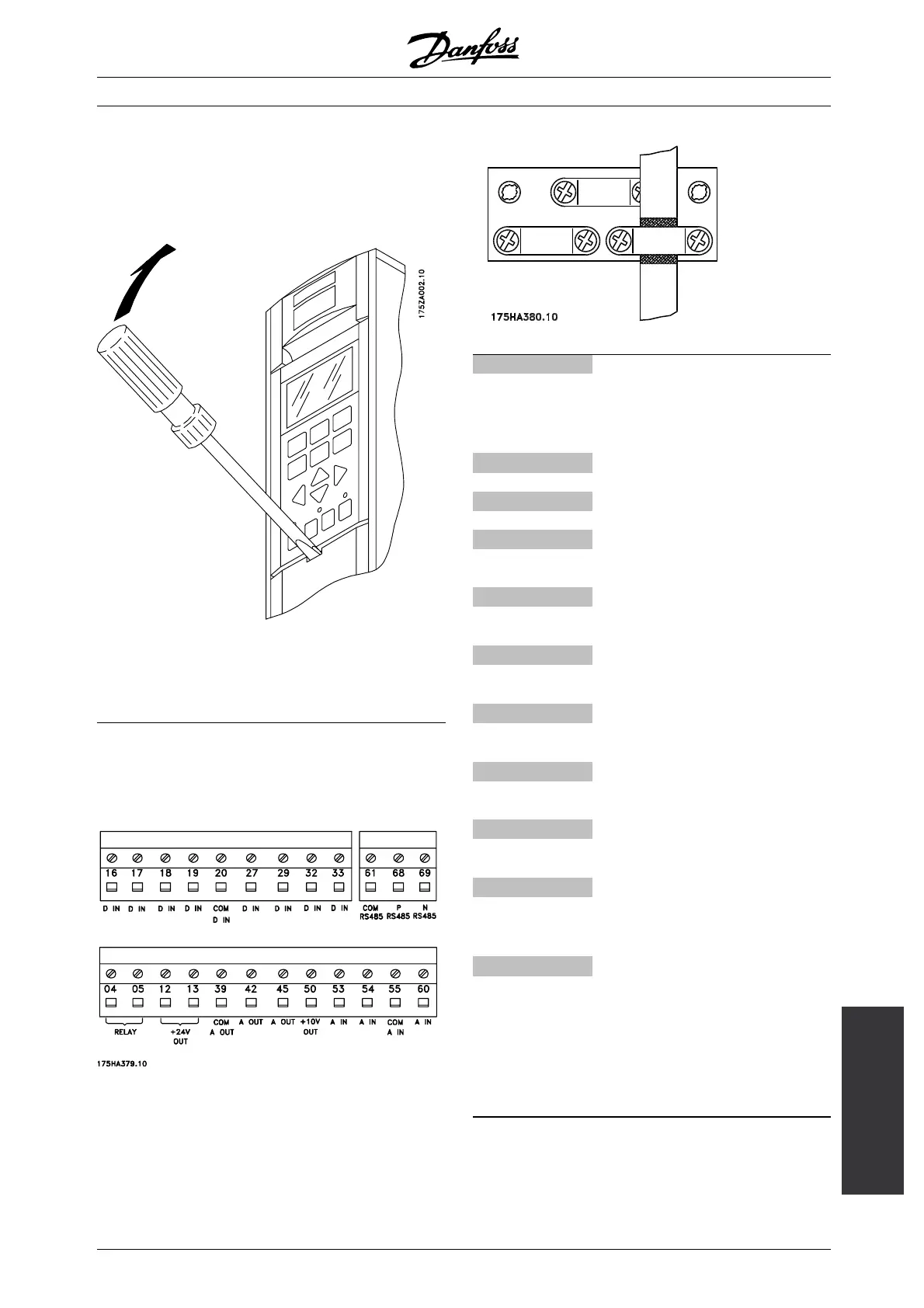
All terminals for the control cables are located under
the protective cover of the frequency converter. The
protective cover (see drawing) can be removed by
means of a pointed object - a screwdriver or similar.
Once the protective cover has been removed, the
actual EMC-correct installation can start. See drawings
in the section, EMC correct installation.
Tightening-up torque: 0.5-0.6 Nm
Screw size: M3
See section earthing of braided screened/armoured
control cables.
No. Function
12, 13 Voltage supply to digital inputs For the 24
VDCtobeusableforthedigitalinputs,
switch 4 on the control card must be
closed. position "ON".
16-33 Digital inputs/encoder inputs
20 Ground for digital inputs
39 Ground for analogue/digital outputs
42, 45 Analogue/digital outputs for indicating
frequency, reference, current and torque
50 Supply voltage to potentiometer and
thermistor 10 V DC
53, 54 Analogue reference input, voltage 0 - ±10
V
55 Ground for analogue reference inputs
60 Analogue reference input, current 0/4-20
mA
61 Termination for serial communication. See
section Bus connection. This terminal is
normally not to be used.
68, 69 RS 485 interface, serial communication.
Where the frequency converter is
connected to a bus, switches 2 and 3
(switches 1- 4) must be closed on the first
and the last frequency converter. On the
remaining frequency converters, switches
2 and 3 must be open. The factory setting
is closed (position "ON").
MG.51.A9.02 - VLT is a registered Danfoss trademark
55
 Loading...