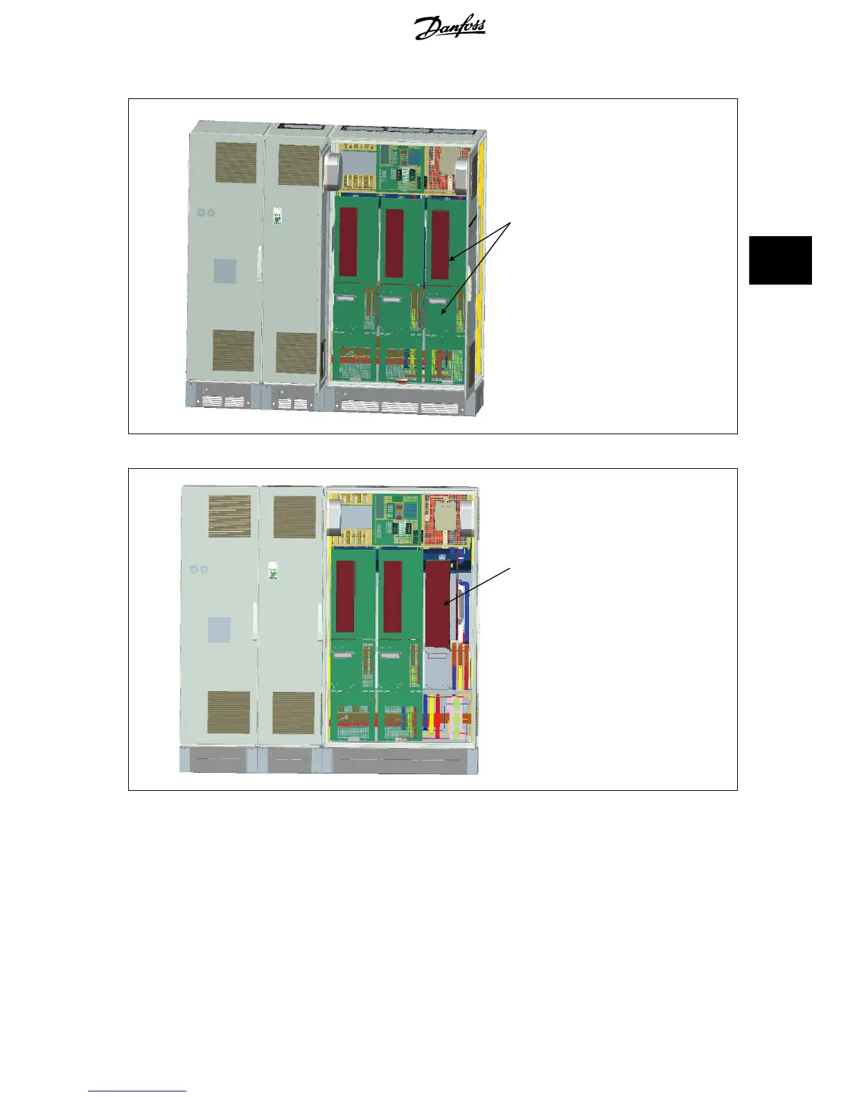
Remove this inductor module
6. After the inductor module is removed, the filter and drive sections can be attached to one another. Four corner brackets and six side brackets
will be required for this operation. They will be included in a bag with the appropriate screws. After the internal brackets are installed, the two
top “L” shaped brackets will be installed to act as load points for moving the complete assembly.
7. Once all the brackets have been installed, the inductor module can be reassembled to its previous location.
8. Now the three mains bus bars, included in as a kit with the drive, can be attached from the filter section to the rectifier section.
VLT AQUA Low Harmonic Drive Operating In-
structions 4 How to Install
MG.20.T1.02 - VLT
®
is a registered Danfoss trademark 27
4
 Loading...


