6 How to Programme the Low Harmonic Drive
6.1 How to Programme the Frequency Converter
6.1.1 Parameter set-up
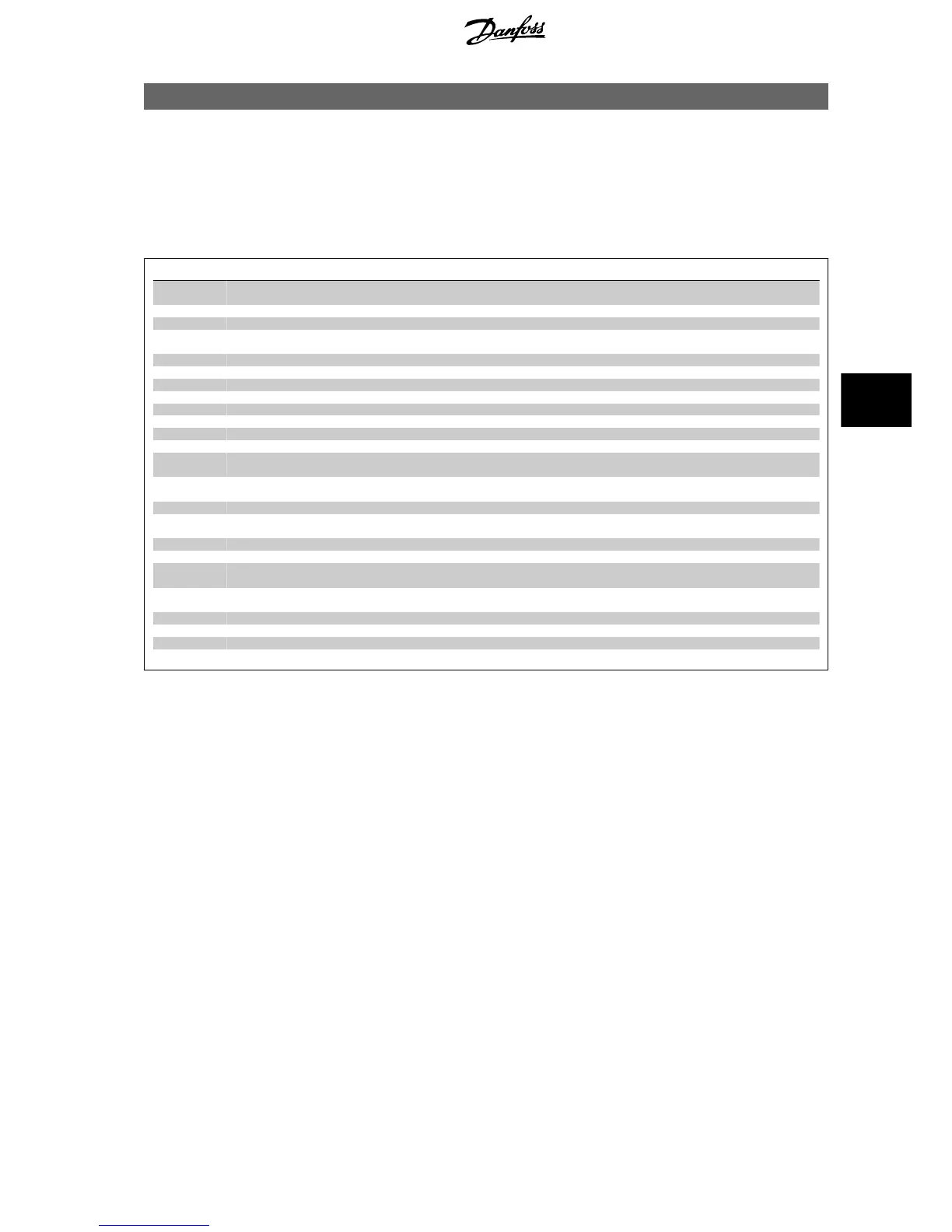
Overview of parameter groups
Group Title Function
0- Operation / Display Parameters related to the fundamental functions of the frequency converter, function of
the LCP buttons and configuration of the LCP display.
1- Load / Motor Parameter group for motor settings.
2- Brakes Parameter group for setting brake features in the frequency converter.
3- Reference / Ramps Parameters for reference handling, definitions of limitations, and configuration of the re-
action of the frequency converter to changes.
4- Limits / Warnings Parameter group for configuring limits and warnings.
5- Digital In/Out Parameter group for configuring the digital inputs and outputs.
6- Analog In/Out Parameter group for configuration of the analog inputs and outputs.
8- Communication and Options Parameter group for configuring communications and options.
9- Profibus Parameter group for Profibus-specific parameters.
10- DeviceNet Fieldbus Parameter group for DeviceNet-specific parameters.
13- Smart Logic Parameter group for Smart Logic Control
14- Special Functions Parameter group for configuring special frequency converter functions.
15- Drive Information Parameter group containing frequency converter information such as operating data,
hardware configuration and software versions.
16- Data Readouts Parameter group for data read-outs, e.g. actual references, voltages, control, alarm,
warning and status words.
18- Info and Readouts This parameter group contains the last 10 Preventive Maintenance logs.
20- Drive Closed Loop This parameter group is used for configuring the closed loop PID Controller that controls
the output frequency of the unit.
21- Extended Closed Loop Parameters for configuring the three Extended Closed Loop PID Controllers.
22- Application Functions These parameters monitor water applications.
23- Time-based Functions These parameters are for actions needed to be performed on a daily or weekly basis, e.g.
different references for working hours/non-working hours.
25- Basic Cascade Controller Functions Parameters for configuring the Basic Cascade Controller for sequence control of multiple
pumps.
26- Analog I/0 Option MCB 109 Parameters for configuring the Analog I/0 Option MCB 109.
27- Extended Cascade Control Parameters for configuring the Extended Cascade Control.
29- Water Application Functions Parameters for setting water specific functions.
31- Bypass Option Parameters for configuring the Bypass Option
Table 6.1: Parameter groups
Parameter descriptions and selections are displayed on the graphic (GLCP) or numeric (NLCP) in the display area. (See Section 5 for details.) Access the
parameters by pressing the [Quick Menu] or [Main Menu] key on the control panel. The quick menu is used primarily for commissioning the unit at start-
up by providing those parameters necessary to start operation. The main menu provides access to all parameters for detailed application programming.
All digital input/output and analog input/output terminals are multifunctional. All terminals have factory default functions suitable for the majority of water
applications but if other special functions are required, they must be programmed in parameter group 5 or 6.
6.1.2 Quick Menu Mode
The GLCP provides access to all parameters listed under the Quick Menus. To set parameters using the [Quick Menu] button:
Pressing [Quick Menu] the list indicates the different areas contained in the Quick menu.
Efficient parameter set-up for water applications
The parameters can easily be set up for the vast majority of the water and wastewater applications only by using the [Quick Menu].
The optimum way to set parameters through the [Quick Menu] is by following the below steps:
1. Press [Quick Setup] for selecting basic motor settings, ramp times, etc.
2. Press [Function Setups] for setting up the required functionality of the frequency converter - if not already covered by the settings in [Quick
Setup].
3. Choose between
General Settings
,
Open Loop Settings
and
Closed Loop Settings.
VLT AQUA Low Harmonic Drive Operating In-
structions
6 How to Programme the Low Harmonic Drive
MG.20.T1.02 - VLT
®
is a registered Danfoss trademark 81
6
 Loading...


