Wiring procedure for enclosure sizes D, E, and F
1. Mount the eldbus connector on the eldbus
option (CAN_L, Drain, CAN_H).
2. Prepare the eldbus cable by stripping a section
of the cable insulation. Keep unshielded wire as
short as possible. For cable specications, refer to
chapter 3.7.1 Cable Specications.
3. Connect the eldbus cable wires to the terminals
according to the colour code of the wires, see
Illustration 3.6.
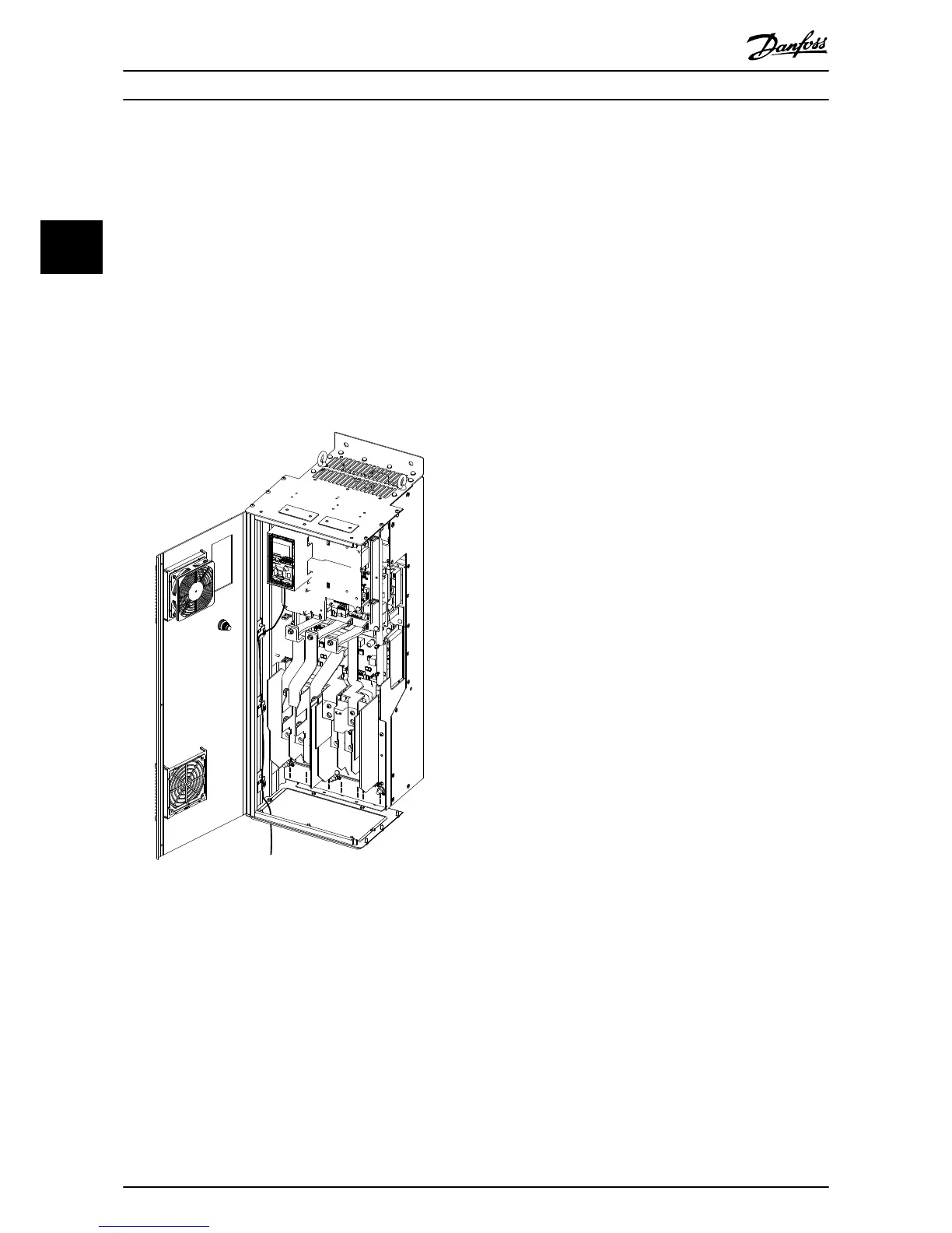
4. Fix the cable screen to the metal base plate using
cable clamp or cable tie, see Illustration 3.9.
5. Tie down the cable and route it with other
control wires inside the unit, see Illustration 3.9.
Illustration 3.9 Wiring for Enclosure Sizes D, E, and F
3.8
Reassembling Cover
1. Mount the new front cover and the LCP.
2. Attach the sticker with the correct product name
to the front cover.
3.9 Applying Power
Follow the instructions in the frequency converter
operating instructions to commission the frequency
converter. The frequency converter automatically detects
the CANopen interface. A new parameter group (Group 10)
appears.
3.10 Checking Network Cabling
1. If the address has not been set via the address
switches, go to parameter 10-02 MAC ID to set the
address.
2. Connect to a running CANopen master.
3. Check that network cabling is correct or not.
Installation
VLT
®
CANopen MCA 105
10 Danfoss A/S © 05/2015 All rights reserved. MG33J402
33
 Loading...


