4 Troubleshooting
4.1 Warnings and Alarms
NOTICE
Refer to the relevant operating instructions for an
overview of warning and alarm types and for the full list
of warnings and alarms.
Alarm word, warning word, and CANopen warning word
are shown on the frequency converter display in hex
format. When there is more than 1 warning or alarm, the
sum of all warnings or alarms is shown. Alarm word,
warning word, and CANopen warning word can also be
displayed using the serial bus in:
•
Parameter 16-90 Alarm Word.
•
Parameter 16-91 Alarm Word 2.
•
Parameter 16-92 Warning Word.
•
Parameter 16-93 Warning Word 2.
4.2 Troubleshooting
4.2.1 LED Status
The 2 bi-colour LEDs on the CANopen card indicate the
status of CANopen communication:
•
The lower LED (NS) indicates the net status.
•
The upper LED (MS) indicates the module status.
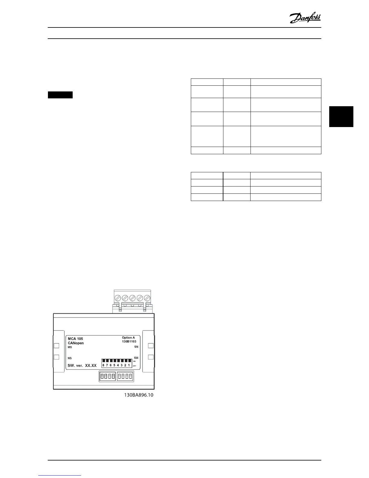
Illustration 4.1 LED Panel VLT
®
CANopen MCA 105
State Red LED Description
No error O No error.
Warning limit
reached
Single ash CAN error counter has reached/
exceeded warning level.
Error control
event
Double ash Node guard event has occurred.
Sync error Triple ash Sync message has not been
received within the congured
timeout (object 0x1006).
Bus o On Device in bus o-state.
Table 4.1 LED: Module Status (MS)
State Red LED Description
Stopped Single ash Device in stopped state.
Pre-operational Triple ash Device in pre-operational state.
Operational On Device in operational state.
Table 4.2 LED: Network Status (NS)
4.2.2 No Communication with the
Frequency Converter
When there is no communication with the frequency
converter, proceed with the following checks:
1. Check that cabling is correct.
Check that the cables are connected to the
correct terminals as shown in Illustration 3.6.
2. Check that the bus connection is terminated at
both ends.
If not, terminate the bus connection with
termination resistors at the initial and
nal nodes.
3. Check that each node connected to the CANopen
network has a unique node ID (address). If 2
devices have the same node ID, it leads to
malfunction in the network.
4. Communication drops out after some time. Check
the installation for correct routing of the
CANopen cables. Check if the screen of the motor
cable is mounted correctly.
5. Communication is unstable. Check
parameter 10-05 Readout Transmit Error Counter
and parameter 10-06 Readout Receive Error
Counter. These 2 parameters have to be close to 0
most of the time. If they show higher values,
check the CANopen cable for interference, wrong
termination, and so on.
Troubleshooting Installation Guide
MG33J402 Danfoss A/S © 05/2015 All rights reserved. 11
4 4
 Loading...


