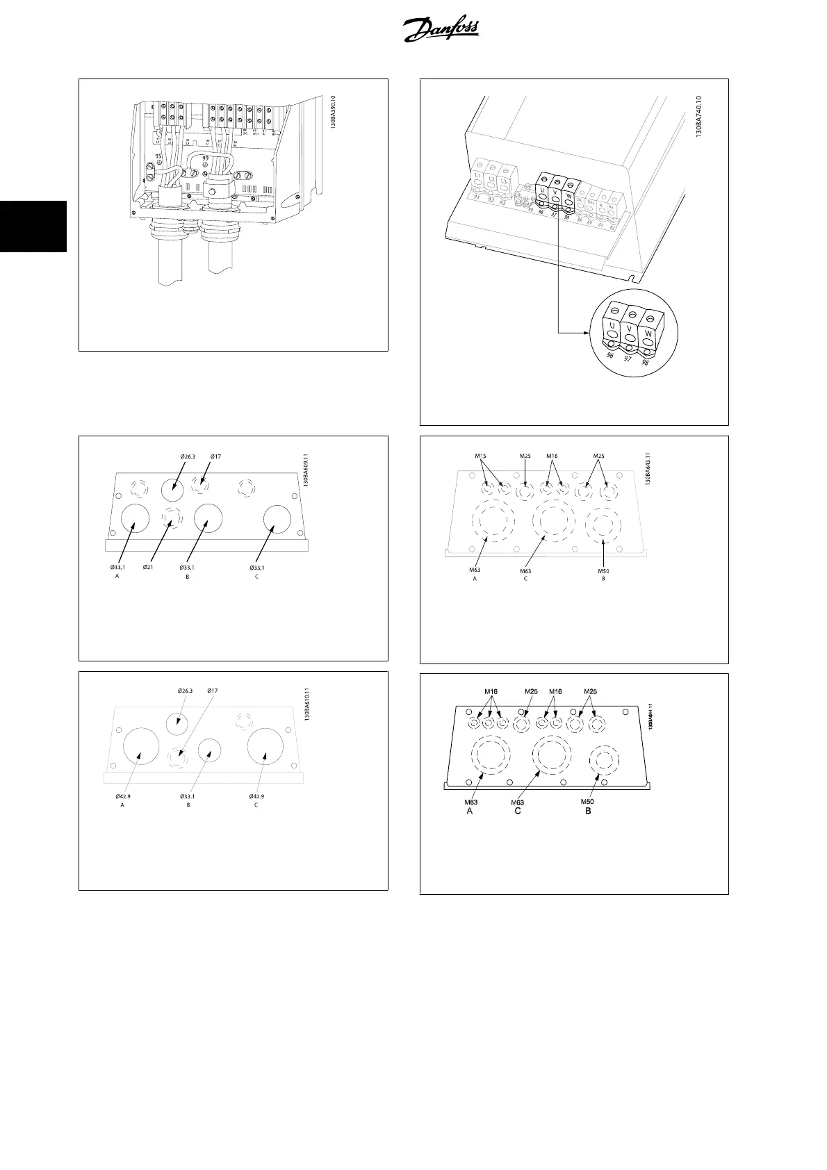
Illustration 3.14: Motor connection frame size C1 and C2 (IP
21/ NEMA Type 1 and IP 55/66/ NEMA Type 12)
Illustration 3.15: Motor connection for frame size C3 and C4.
Illustration 3.16: Cable entry holes for frame size B1. The
suggested use of the holes are purely recommendations and
other solutions are possible.
Illustration 3.17: Cable entry holes for frame size B2. The
suggested use of the holes are purely recommendations and
other solutions are possible.
Illustration 3.18: Cable entry holes for frame size C1. The
suggested use of the holes are purely recommendations and
other solutions are possible.
Illustration 3.19: Cable entry holes for frame size C2. The
suggested use of the holes are purely recommendations and
other solutions are possible.
Unused cable entry holes can be sealed with rubber grommets (for IP 21). More information and ordering numbers can be found in the Design Guide.
3 How to Install
VLT
®
AutomationDrive FC 300 Operating
Instructions
28
MG.33.AG.02 - VLT
®
is a registered Danfoss trademark
3
 Loading...


