4.4 Parameter Lists
Changes during operation
”TRUE” means that the parameter can be changed while the frequency converter is in operation and “FALSE” means that the it must be stopped before
a change can be made.
4-Set-up
'All set-up': the parameters can be set individually in each of the four set-ups, i.e. one single parameter can have four different data values.
’1 set-up’: data value will be the same in all set-ups.
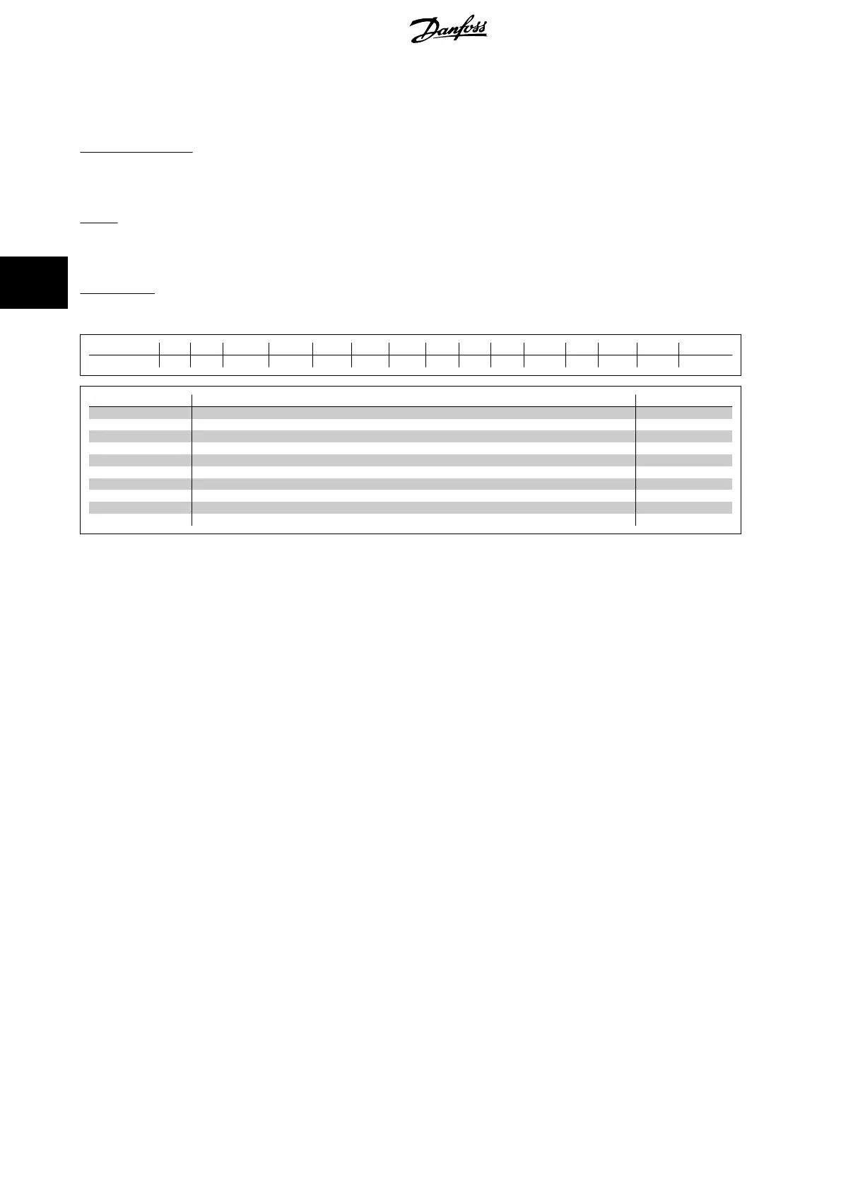
Conversion index
This number refers to a conversion figure used when writing or reading to and from the frequency converter.
Conv. index 100 67 6 5 4 3 2 1 0 -1 -2 -3 -4 -5 -6
Conv. factor 1 1/60 1000000 100000 10000 1000 100 10 1 0.1 0.01 0.001 0.0001 0.00001 0.000001
Data type Description Type
2 Integer 8 Int8
3Integer 16 Int16
4 Integer 32 Int32
5 Unsigned 8 Uint8
6 Unsigned 16 Uint16
7 Unsigned 32 Uint32
9 Visible String VisStr
33 Normalized value 2 bytes N2
35 Bit sequence of 16 boolean variables V2
54 Time difference w/o date TimD
See the frequency converter
Design Guide
for further information about data types 33, 35 and 54.
4 How to Programme
VLT
®
AutomationDrive FC 300 Operating
Instructions
70
MG.33.AG.02 - VLT
®
is a registered Danfoss trademark
4
 Loading...


