VLT
®
FCD Series
■ Mechanical installation
Please pay attention to the requirements
t
hat apply to integration and remote
m
ounting. These must be complied with
t
o avoid serious injury or damage, especially when
installing large units.
The FCD 300 is consists of two parts: The installa-
tion part and the The electronics part.
The two parts must be separated, and the installa-
tion part is to be mounted first. After wiring, the
electronics is to be fixed to the installation part by
the attached 6 screws. For compressing the gasket
the screws must be tightened with 3 Nm.
The FCD 300 can be applied as following:
- Stand alone mounted close to the motor
- Motor mounted
or might be delivered pre mounted on a Danfoss
Bauer (geared) motor. Please contact the Danfoss
Bauer sales organisation for further information.
The frequency converter is cooled by means of air
circulation. For the unit to be able to release its cool-
ing air, the minimum free distance above and below
the unit must be m
inimum 100 mm. To protect the
unit from overheating, it must be ensured that the
ambient temperature does not rise above the max.
temperature stated for the frequency converter and
that the 24-hour average temperature is not ex-
ceeded. The max. temperature and 24-hour average
can be seen in
General technical data. If the ambi-
ent temperature is higher, derating of the frequency
converter is to be carried out. See Derating for am-
bient temperature. Please note that the service life
of the frequency converter will be reduced if derating
for ambient temperature is not considered.
S
tand alone mounting ("wall mounting")
For best cooling the unit should be mounted verti-
cally, however where space limitations require it,
horizontal mounting is allowable. The integrated 3
wall mounting brackets in the wall mounting version
can be used for fixing the installation box to the
mounting surface, keeping a distance for possible
cleaning between the box and the mounting surface.
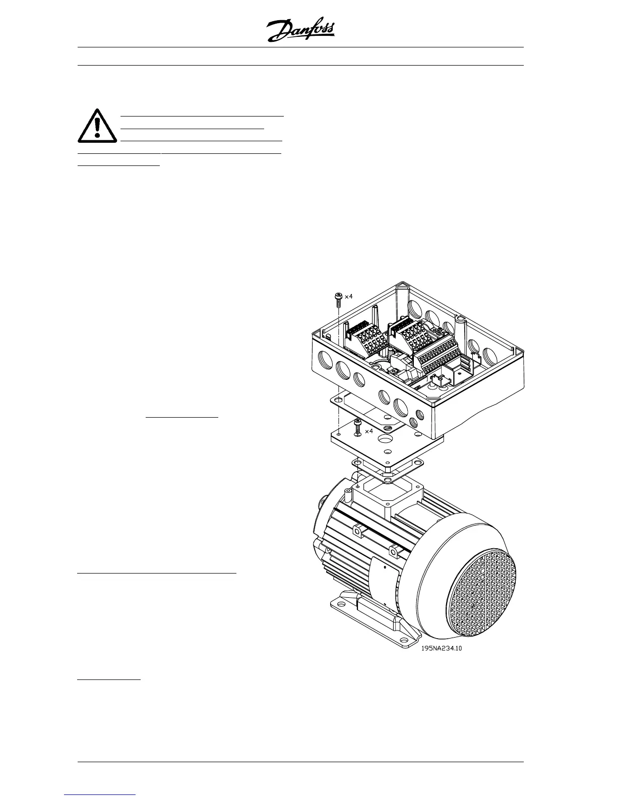
M
otor mounting
The installation box should be mounted on the sur-
face of the motor frame, typically instead of the
motor terminal box. The motor/geared motor may be
mounted with the shaft vertically or horizontally . The
unit mustnot be mounted upside down (the heat sink
pointing down). The cooling of the electronics is in-
dependent on the motor cooling fan. For motor
mounting (non Danfoss Bauer motors) an adaptor
plate should usually be applied. For that purpose a
neutral plate incl gasket and screws for attaching to
the installation box. is available. The appropriate
drillings and gasket for the motor housing are ap-
plied locally. Please make sure, that the mechanical
strength of the mounting screws and the threads are
sufficient for the application. The specified resis-
tance against mechanical vibrations does not cover
the mounting onto a non Danfoss Bauer motor, as
the stability of the motor frame and threads are out-
side Danfoss Drive’s control and responsibility .
Please be aware, that the frequency converter may
not be used to lift the motor/geared motor.
MG.04.A1.02 - VLT is a registered Danfoss trade mark
30
 Loading...


