Ring topology can increase the availability of an Ethernet
network.
For ring topology:
•
Install a special switch (redundancy manager)
between the PLC and the frequency converters.
•
Configure the redundancy manager switch to
clearly define the ports that connect to the ring.
The redundancy manger sends out test frames on its 2
ports where the ring is connected. When no test frames
are lost, the redundancy manager keeps the ring in
operational. If the switch detects a fault in the ring, it
reconfigures the ring into 2 lines instead. The transition
time from 1 ring into 2 lines is up to 500 ms, depending
on the components installed in the ring. Set the timing of
the PLC to ensure that the transition time does not lead to
timeout fault.
NOTICE
For ring/redundant line topology, ensure that the
redundancy manager switch supports detection of loss
of line topology. The switch inside the PROFINET
interface does not support this detection.
Recommended design rules
•
Pay special attention to active network
components when designing an Ethernet
network.
•
For line topology, a small delay is added with
each additional switch in the line. See Table 3.1
for more information.
•
Do not connect more than 50 frequency
converters in series. Exceeding this limit can
result in unstable or faulty communication.
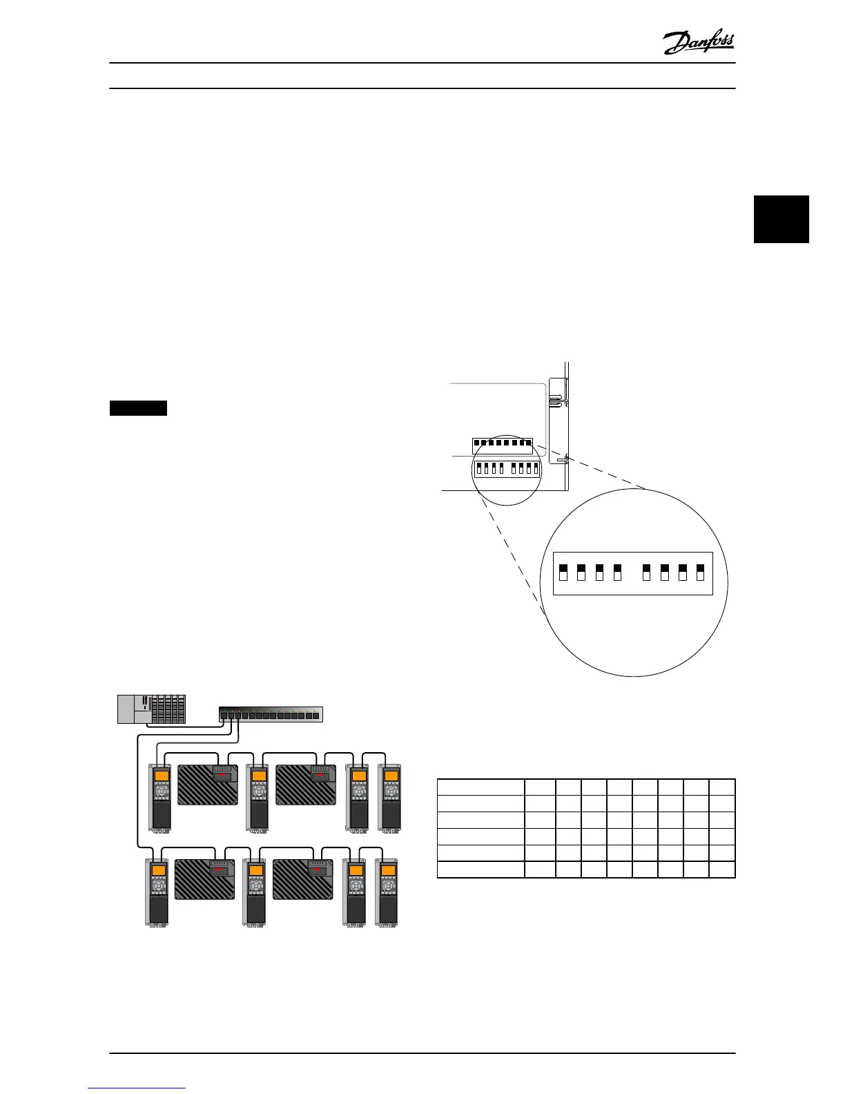
Illustration 3.8 Recommended Design Rules
3.7 Setting Address Switches
The option has address switches that are used to set the
station name (host name). This feature is available from
firmware version 3.00 onwards.
•
When all switches are set to On, or all are set to
OFF, change the station name via 12-08 Host
Name or via DCP command.
•
In all other combinations, the address switches
have priority over the parameter setting. The
station name is set based on the value in
15-40 FC Type, and a 3-digit number selected
from the DIP settings.
Illustration 3.9 Address Switches
Use the address switches to set the 253 different station
names according to Table 3.2:
Switch 8 7 6 5 4 3 2 1
12-08 Host Name
+128 +64 +32 +16 +8 +4 +2 +1
FC-302-005 OFF OFF OFF OFF OFF ON OFF ON
FC-302-035 OFF OFF ON OFF OFF OFF ON ON
FC-302-082 OFF ON OFF ON OFF OFF ON OFF
FC-302-212 ON ON OFF ON OFF ON OFF OFF
Table 3.2 Host Names Setting (FC 302 used in this example)
The station name change comes into effect at the next
power-up. Read the station name in 12-08 Host Name.
Installation
Installation Guide
MG90U402 Danfoss A/S © Rev. 07/2014 All rights reserved. 9
3 3

 Loading...


