3.8.3 Wiring Procedures
Wiring pocedure for enclosure types A1-A3
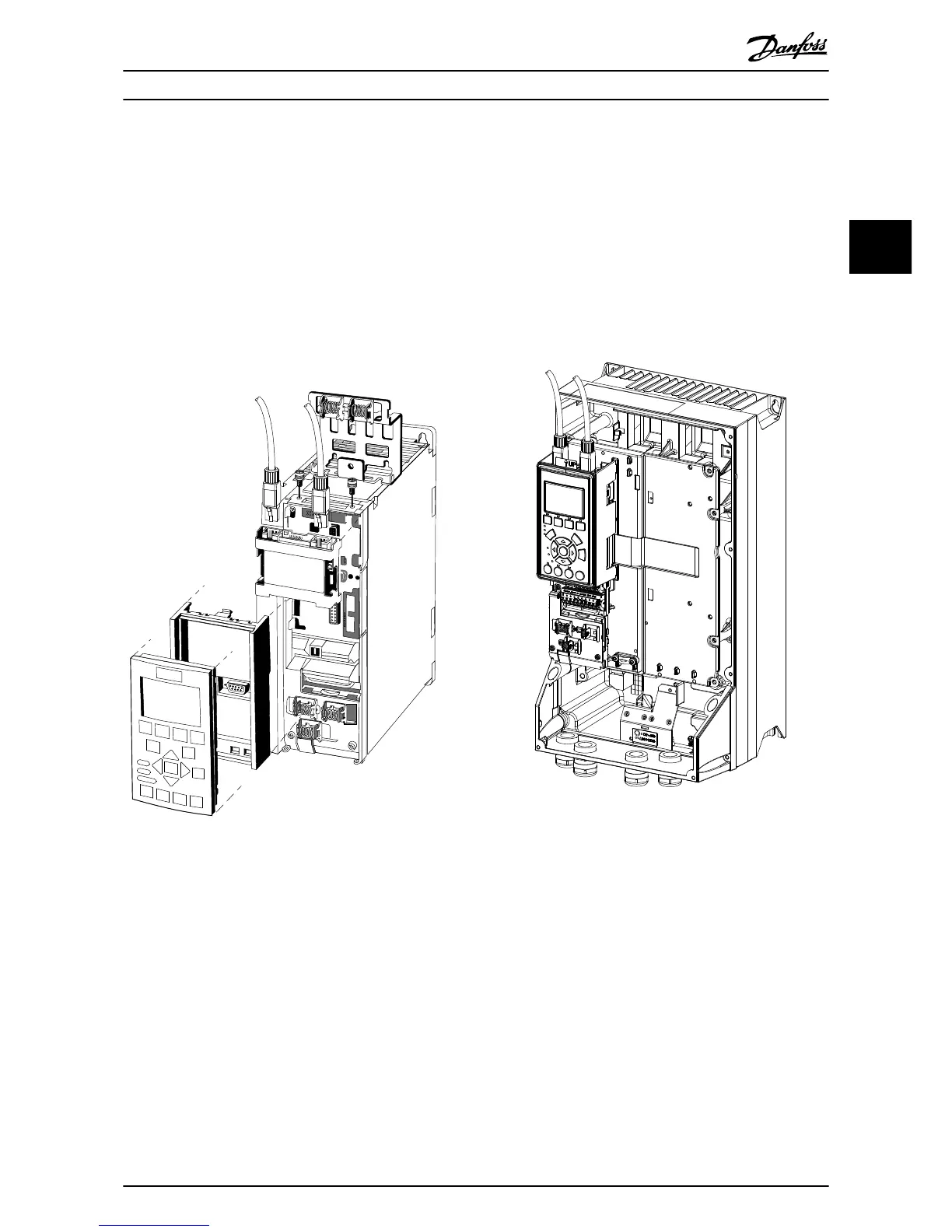
1. Mount the pre-configured cable wires with the
connectors on the fieldbus option. For A1 and A2
enclosures, mount the supplied strain relief on
top of the frequency converter with 2 screws, as
shown in Illustration 3.10. For cable specifications,
refer to chapter 3.8.2 Cable Specifications.
2. Position the cable between the spring loaded
metal clamps, to establish mechanical fixation
and electrical contact between cable and ground.
EtherNet Port1 EtherNet Port2
OPCPRT
Option
A
EtherNet/IP
MS
MS1 MAC-00-1B-08-00-00-22
MS2
SW.ver.
Illustration 3.10 Wiring for Enclosure Types A1-A3
Wiring procedure for enclosure types A4-A5, B1-B4, and
C1-C4
1. Push the cable through the cable glands.
2. Mount the pre-configured cable wires with the
connectors on the fieldbus option. For cable
specifications, refer to chapter 3.8.2 Cable Specifi-
cations.
3. Fix the cable to the metal base plate using the
springs, see Illustration 3.11.
4. Tighten the cable glands securely.
Illustration 3.11 Wiring for Enclosure Types A4-A5, B1-B4, and
C1-C4
Installation Installation Guide
MG90U402 Danfoss A/S © Rev. 07/2014 All rights reserved. 11
3 3

 Loading...


