Matrix-2000™ Reference Manual
1
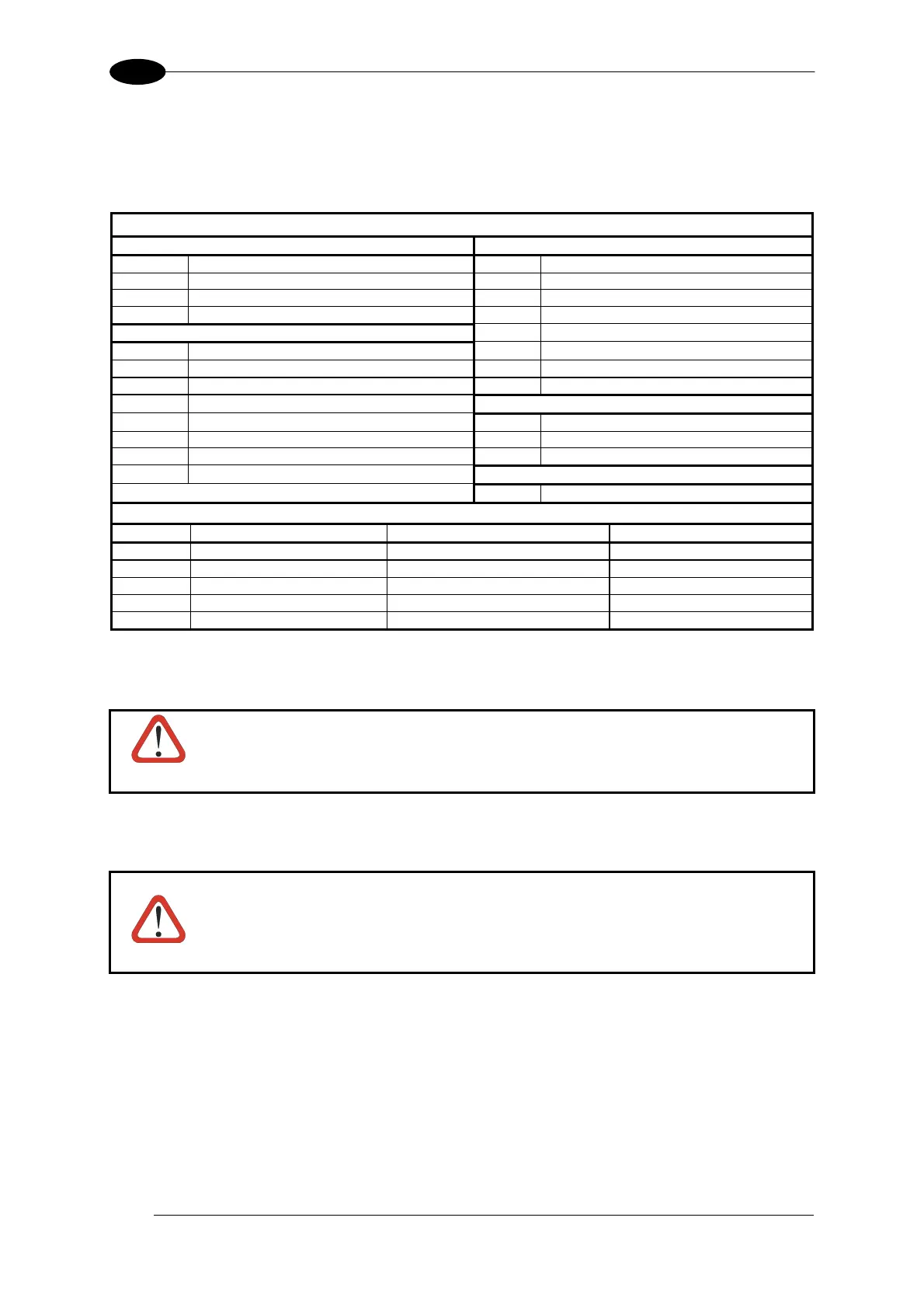
CBX100/CBX500 Pinout for Matrix-2000™
The table below gives the pinout of the CBX100/CBX500 terminal block connectors. Use this
pinout when the Matrix-2000™ reader is connected by means of the CBX100/CBX500:
CBX100/500 Terminal Block Connectors
Input Power Outputs
Vdc Power Supply Input Voltage + +V Power Source - Outputs
GND Power Supply Input Voltage - -V Power Reference - Outputs
Earth Protection Earth Ground O1+ Output 1 +
O1- Output 1 -
Inputs
O2+ Output 2 +
+V Power Source – External Trigger O2- Output 2 -
I1A External Trigger A (polarity insensitive) O3A Output 3 + (CBX500 only – polarity sensitive)
I1B External Trigger B (polarity insensitive) O3B Output 3 - (CBX500 only – polarity sensitive)
-V Power Reference – External Trigger
Auxiliary Interface
+V Power Source – Inputs TX Auxiliary Interface TX
I2A Input 2 A (polarity insensitive) RX Auxiliary Interface RX
I2B Input 2 B (polarity insensitive) SGND Auxiliary Interface Reference
-V Power Reference – Inputs
Shield
Shield Network Cable Shield
Main Interface
RS232 RS485 Full-Duplex RS485 Half-Duplex
TX TX+ RTX+
RTS TX- RTX-
RX
*RX+
CTS
*RX-
SGND SGND SGND
* Do not leave floating, see par. 4.2.2 for connection details.
CAUTION
Do not connect GND and SGND to different (external) ground references.
GND and SGND are internally connected through filtering circuitry which
can be permanently damaged if subjected to voltage drops over 0.8 Vdc.
CAUTION
If Matrix-2000™ is connected to a CBX with a BM100 Backup Module, then
the Matrix-2000™ 9-pin Auxiliary port connector cannot be used for
communication (i.e. configuration through VisiSet™). In this case use the
Auxiliary port 9-pin connector inside the CBX.
2

 Loading...