5. DST_PA2 (PCIe/NVMe connector) 6. BP_PWR_1 (backplane power and signal cable to system
board)
7. DST_PB2 (PCIe/NVMe connector)
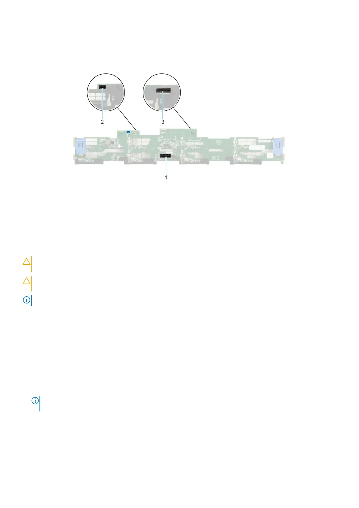
Figure 48. 8 x 3.5-inch SAS/SATA backplane
1. BP_PWR_1 (PERC to backplane)
2. BP_DST_SA1 (SAS/SATA connector)
3. Front mounted front PERC connector
Removing the drive backplane
Prerequisites
CAUTION:
To prevent damage to the drives and backplane, remove the drives from the system before removing
the backplane.
CAUTION: Note the number of each drive and temporarily label them before you remove the drive so that you
can reinstall them in the same location.
NOTE: The procedure to remove the backplane is similar for all backplane configurations.
1. Follow the safety guidelines listed in the Safety instructions.
2. Follow the procedure listed in the Before working inside your system.
3. Remove the air shroud.
4. Remove the drive backplane cover.
5. Remove all the drives.
6. If installed, disconnect the optical drive signal and power cables from the system.
7. Disconnect the drive backplane cables from the connectors on the system board.
Steps
1. Press the blue release tabs to disengage the drive backplane from the hooks on the system.
2. Lift the drive backplane out of the system.
NOTE:
To avoid damaging the backplane, ensure that you move the control panel cables from the cable routing clips
before removing the backplane.
56 Installing and removing system components
 Loading...


