Palm-rest and keyboard assembly
Removing the palm-rest and keyboard assembly
1. Follow the procedure in Before working inside your computer.
2. Remove the base cover.
3. Remove the battery.
4. Remove the WLAN card.
5. Remove the hard drive.
6. Remove the GPU fan.
7. Remove the CPU fan.
8. Remove the speakers.
9. Remove the display assembly.
10. Remove the I/O board.
11. Remove the power button with fingerprint reader.
12. Remove the power-adapter port.
13. Remove the touchpad.
14. Remove the system board.
NOTE:
The system board can be removed along with the heat sink.
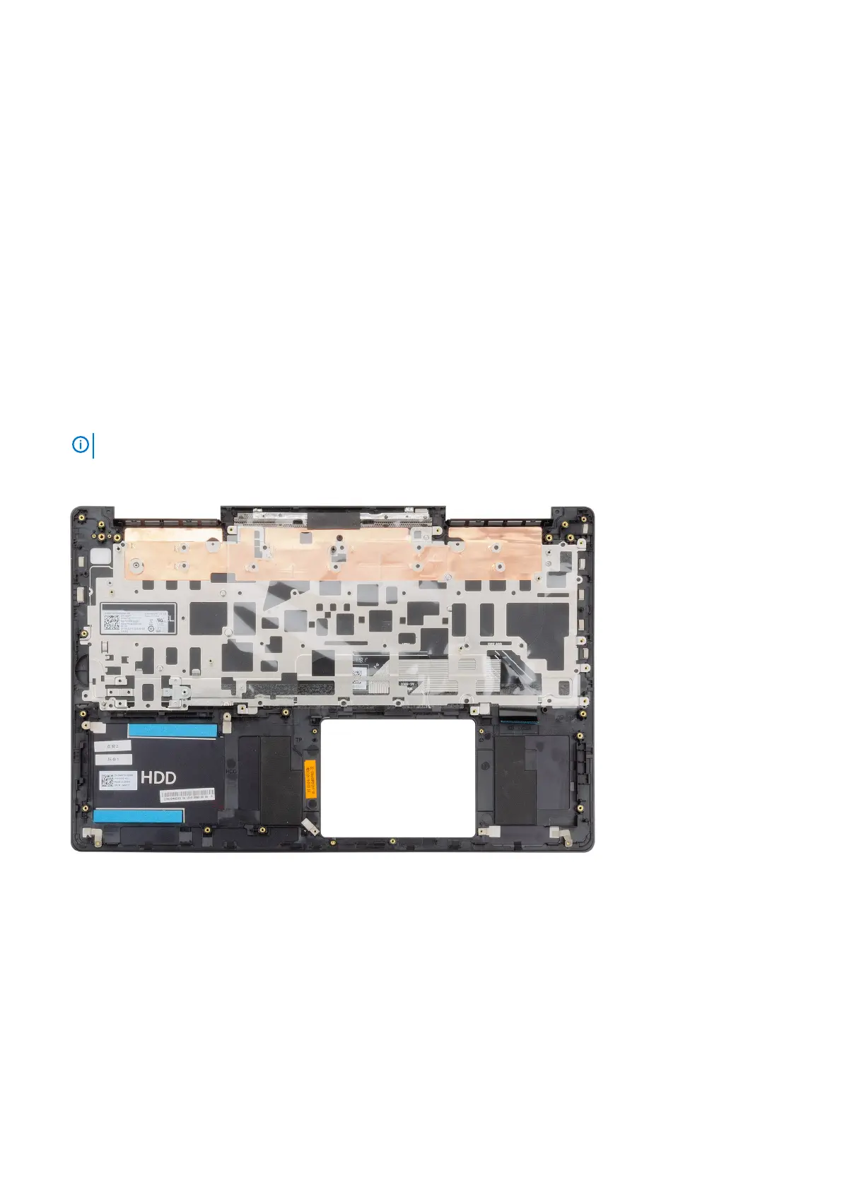
The figure indicates the location of the palm-rest and keyboard assembly and provides a visual representation of the removal procedure.
After performing the steps in the pre-requisites, we are left with the palm-rest and keyboard assembly.
Installing the palm-rest and keyboard assembly
If you are replacing a component, remove the existing component before performing the installation procedure.
The figure indicates the location of the palm-rest and keyboard assembly and provides a visual representation of the installation procedure.
58
Removing and installing components
 Loading...