41 Dell EMC Networking with Isilon Front-End Deployment and Best Practices Guide | version 1.0
7 Configuration of Layer 2 Topology
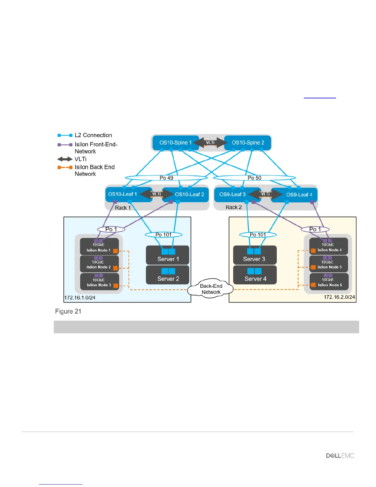
This section will cover the configuration of the layer 2 topology. In the example provided there are three Isilon
nodes connected to each leaf pair as well as two Dell PowerEdge servers that will be consuming the storage.
The connections from the spine switches to the OS10EE leaf pair will be configured in port channel 49, while
the connections to the OS9 leaf pair will be configured in port channel 50. The two spine switches will be
configured in a VLT. The benefits and draw backs of a L2 configuration were referenced in Chapter 4.1. The
Isilon nodes will all connect to each switch in the leaf pair using an LACP port channel for each node, the
connections for the Windows servers will be similarly configured. Also, each Isilon Node will be connected on
the back-end network through two InfiniBand switches, creating one single six node cluster.
L2 topology
Note: The configuration files for every switch in this topology are listed in the attachments section.
7.1 Configuration of Z9100-ON OS10EE Spine Switches
The configuration of the example used in this guide will begin with the two Z9100-ON’s Spine1 and Spine2 as
seen in Figure 22.
 Loading...