EasyManuals Logo
Home>Dell>Server>PowerEdge R320

Dell PowerEdge R320 User Manual

Dell PowerEdge R320
143 pages
To Next Page IconTo Next Page
To Previous Page IconTo Previous Page
Page #101 background imageLoading...
Page #101 background image
WARNING: The heat sink is hot to touch for some time after the system has been powered down. Ensure
that you do not touch the heat sink while removing the system board.
g) heat sink and processor
h) internal dual SD module
NOTE: It is recommended that you remove the power distribution board before removing the system board
from the chassis.
5. Disconnect all other cables from the system board.
CAUTION: Take care not to damage the system identification button while removing the system board from
the chassis.
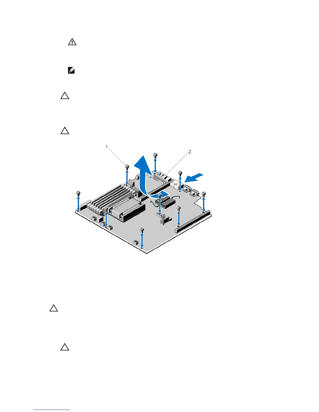
6. Remove the nine screws on the system board and slide the system board toward the front of the system.
7. Hold the system board by its edges and lift the system board out of the chassis.
CAUTION: Do not lift the system board assembly by grasping a memory module, processor, or other
components.
Figure 61. Removing and Installing the System Board
1. screws (9)
2. system board
Installing The System Board
CAUTION: Many repairs may only be done by a certified service technician. You should only perform
troubleshooting and simple repairs as authorized in your product documentation, or as directed by the online or
telephone service and support team. Damage due to servicing that is not authorized by Dell is not covered by your
warranty. Read and follow the safety instructions that came with the product.
1. Unpack the new system board assembly.
CAUTION: Do not lift the system board assembly by grasping a memory module, processor, or other
components.
101

Table of Contents

Other manuals for Dell PowerEdge R320

Questions and Answers:

Question and Answer IconNeed help?

Do you have a question about the Dell PowerEdge R320 and is the answer not in the manual?

Dell PowerEdge R320 Specifications

General IconGeneral
Bus typeQPI
SteppingM1
FSB ParityNo
Scalability2S
Processor codeSR0LS
Processor cache10 MB
Processor cores4
Processor modelE5-2403
System bus rate6.4 GT/s
Processor seriesIntel Xeon E5-2400
Processor socketLGA 1356 (Socket B2)
Processor codenameSandy Bridge EN
Motherboard chipsetIntel C600
Processor frequency1.8 GHz
Processor cache typeSmart Cache
Processor lithography32 nm
Processor manufacturerIntel
Processor package size45 x 42.5 mm
Processor front side bus- MHz
Processor operating modes64-bit
ECC supported by processorYes
Supported instruction setsAVX
Thermal Design Power (TDP)80 W
Number of processors installed1
Maximum number of PCI Express lanes24
Memory types supported by processorDDR3-SDRAM
Memory channels supported by processorTriple
Memory clock speeds supported by processor800, 1066 MHz
Memory bandwidth supported by processor (max)25 GB/s
Maximum internal memory supported by processor375 GB
HDD size3.5 \
HDD speed7200 RPM
HDD capacity1000 GB
HDD interfaceSerial ATA
Optical drive typeDVD-RW
Total storage capacity2000 GB
Maximum storage capacity16 TB
Number of HDDs installed2
Memory slots6x DIMM
Internal memory4 GB
Memory clock speed1333 MHz
Maximum internal memory96 GB
Cabling technology10/100/1000Base-T(X)
PS/2 ports quantity-
USB 2.0 ports quantityUSB 2.0 ports have a data transmission speed of 480 Mbps, and are backwards compatible with USB 1.1 ports. You can connect all kinds of peripheral devices to them.
PCI Express slots version3.0
Power supply350 W
Compatible operating systemsMicrosoft Windows Server 2012 \\r Microsoft Windows Server 2012 Essentials\\r Microsoft Windows Server 2008 R2 \\r Novell SUSE Linux Enterprise Server\\r Red Hat Enterprise Linux
Sustainability certificatesENERGY STAR
Chassis typeRack (1U)
Processor ARK ID64615
Intel Identity Protection Technology version0.00
Weight and Dimensions IconWeight and Dimensions
Width- mm

Related product manuals