- 4 -
Installation
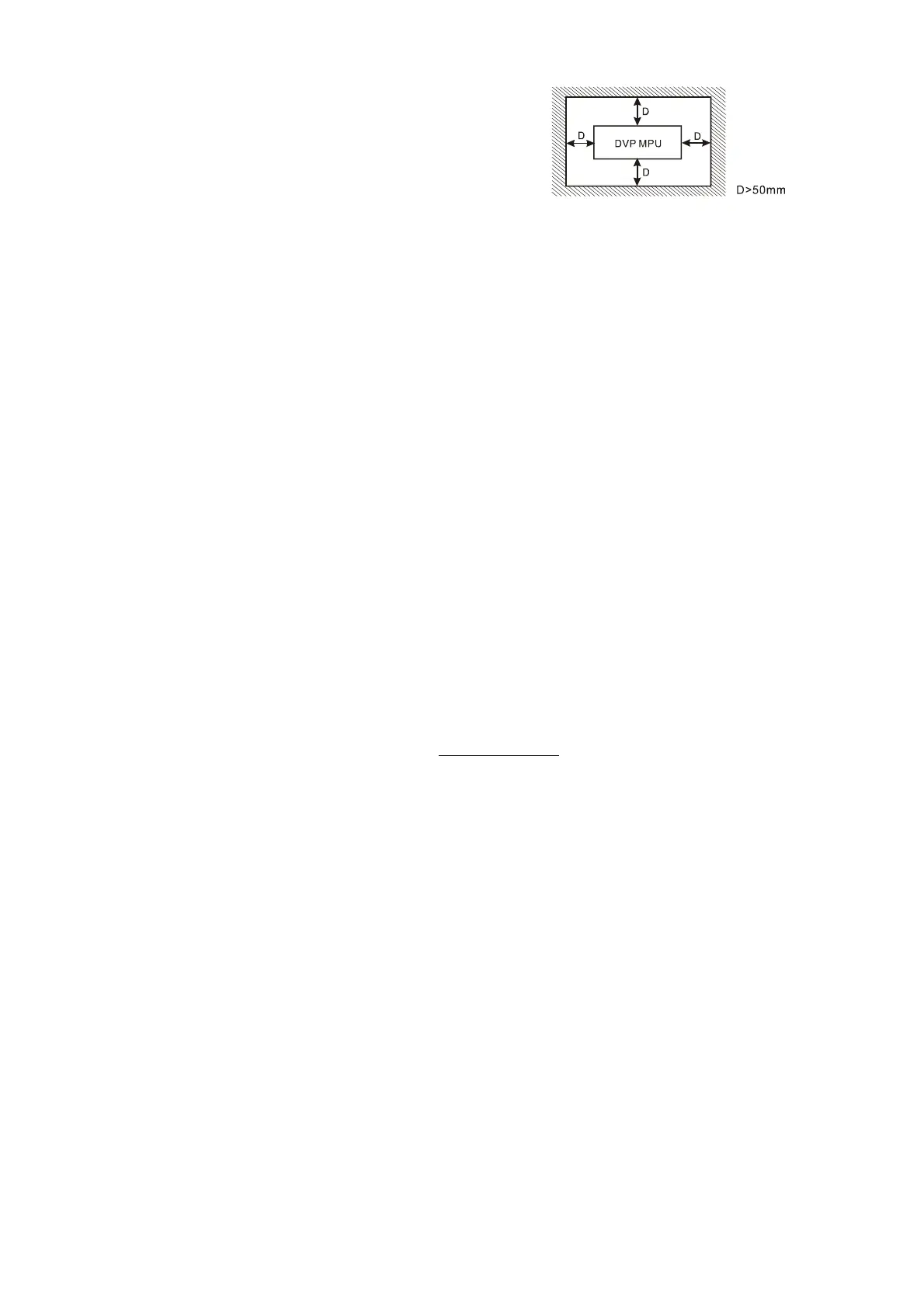
Please install the PLC in an enclosure with
sufficient space around it to allow heat dissipation,
as shown in the figure.
y Direct Mounting: Please use M4 screw
according to the dimension of the product.
y DIN Rail Mounting: When mounting the PLC to
35mm DIN rail, be sure to use the retaining clip to stop any side-to-side movement o
the PLC and reduce the chance of wires being loose. The retaining clip is at the
bottom of the PLC. To secure the PLC to DIN rail, pull down the clip, place it onto the
rail and gently push it up. To remove the PLC, pull the retaining clip down with a fla
t
screwdriver and gently remove the PLC from DIN rail.
Wiring
1. Use the 12-24 AWG single-core bare wire or the multi-core wire for the I/O wiring.
The PLC terminal screws should be tightened to 3.80 kg-cm (3.30 in-lbs) and
please use 60/75°C copper conductor only.
2. DO NOT wire empty terminal. DO NOT place the input signal wire and output
power wire in the same wiring circuit.
3. DO NOT drop tiny metallic conductor into the PLC while screwing and wiring.
y Please attach the dustproof sticker to the PLC before the installation to prevent
conductive objects from dropping in.
y Tear off the sticker before running the PLC to ensure normal heat dissipation.
Power Supply
The power input type for DVP-ES2 model is AC input. When operating DVP-ES2,
please note the following points:
1. The range of the input voltage should be 100 ~ 240VAC. The power supply should
be connected to L and N terminals. Please note that
wiring AC110V or AC220V to
+24V output terminal or digital input points will result in serious damage on the PLC.
2. The AC power inputs for the MPU and the digital I/O module should be ON or OFF at
the same time.
3. Use 1.6mm wire (or longer) for the grounding of the PLC.
4. The power shutdown of less than 10ms will not affect the operation of the PLC.
However, power shutdown time that is too long or the drop of power supply voltage
will stop the running of the PLC, and all outputs will go “OFF”. When the power
returns to normal status, the PLC will automatically resume operation. (Care should
be taken on the latched auxiliary relays and registers inside the PLC when
programming.)
5. The +24V output is rated at 0.5A from MPU. DO NOT connect other external power
supplies to this terminal. Every input terminal requires 5 ~ 7mA to be driven; e.g. the
16-point input will require approximately 100mA. Therefore, +24V terminal cannot
give output to the external load that is more than 400mA.
Safety Wiring
In PLC control system, many devices are controlled at the same time and actions of any
device could influence each other, i.e. breakdown of any device may cause the
breakdown of the entire auto-control system and danger. Therefore, we suggest you
wire a protection circuit at the power supply input terminal. See the figure below.
 Loading...


