213777, Rev. A
www. s p e c s e l e c t . c o m
Page 7
If Hardwire Operated
• Attach hardwire converter supplied to the 24VAC power source using the wire
nuts provided.
• Attach converter to the sensor module using the snap connector. With power
to ushometer, there will be a sequence of red lights that strobe across the
sensing lens window which signies that the valve is now in operation mode.
• 4” Plate Models - Connect the female connectors from the sensor module to the solenoid ush valve. A 1,220 mm (48“) solenoid
extension cord has been provided, if required, to make the connection between the sensor module and solenoid. Make sure to correctly
match the wire colours on the sensor module to the solenoid.
• 14” Plate Models - Connect the female connectors from the sensor module to the solenoid on the ush valve. Make sure to correctly
match the wire colours on the sensor module to the solenoid.
• If the factory default settings for the sensor are not suitable, refer to step 4 for sensor adjustments.
• Attach sensor plate to the box using the 4 vandalproof screws provided.
If Battery Operated
• Install 4 “C” cell batteries provided into the battery holder and attach the holder to the sensor module using the battery clip. Use the +/-
on the battery holder for correct battery positioning. With power to ushometer, there will be a sequence of red lights that strobe across
the sensing lens window which signies that the valve is now in operation mode.
• 4” Plate Models - Connect the female connectors from the sensor module to the solenoid ush valve. A 1,220 mm (48“) solenoid
extension cord has been provided, if required, to make the connection between the sensor module and solenoid. Make sure to correctly
match the wire colours on the sensor module to the solenoid.
• 4” Plate Models - Install battery holder into the back of the box and attach the sensor plate to the box using the 4 vandalproof screw
provided.
• 14” Plate Models - Connect the female connectors from the sensor module to the solenoid on the ush valve. Make sure to correctly
match the wire colours on the sensor module to the solenoid.
• If the factory default settings for the sensor are not suitable, refer to step 4 for sensor adjustments.
• 14” Plate Models - Attach battery holder with the 2 way tape provided, to a secure location on the wall framing, etc.
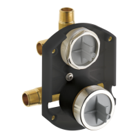
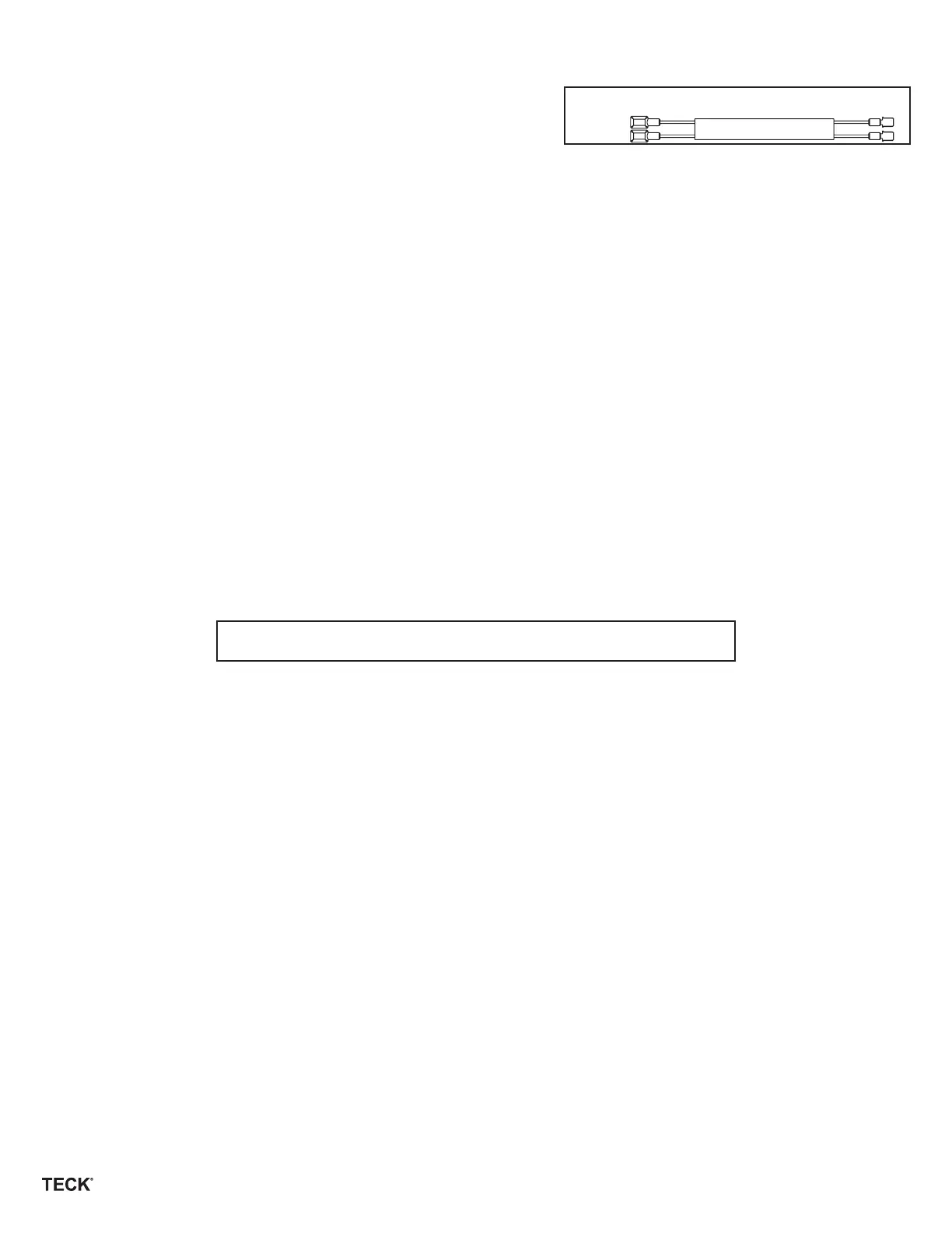
STEP 2 - INSTALL SENSOR PLATE
Sensor Extension Cord
Fig. 2
STEP 3 - OPERATION MODE
A sequence of red lights that strobe across the sensing lens window will signify that the valve is now in operation mode.
Once in operation mode, if factory settings are preferred, no further action is required and the valve installation is complete.
Factory pre-set functions are:
Water closet sensing distance of 40” and ush delay is 4 seconds.
Urinal sensing distance of 20”, 24 hour ush is o, and no ush delay.
Once in operation mode, if adjustments are preferred, installer must move into set up mode.
FUNCTION AND TROUBLESHOOTING LIGHTS
BATTERY VERSION: NO LIGHTS-NO POWER
Check that the 4 “C” batteries are positioned properly in the battery holder. Use the +/- on the battery holder for correct positioning. If the
batteries are positioned correctly but there are still no lights, replace with 4 new “C” Alkaline batteries.*
HARDWIRE VERSION: NO LIGHTS-NO POWER
Check that the 24VAC transformer has power on the incoming 120VAC side. (Transformer breaker is turned on.)
Check the connection of the ushometer wires to 24VAC transformer.
Check that the connection of the hardwire converter is made to the electronic board within the electronic ush valve housing.
For further technical assistance, call Delta Commercial Technical Service at 1-800-387-8277 (Canada) or 1-877-509-2680 (U.S.A.).
1. Start-Up: When the system is rst powered, a sequence of red lights that strobe across the sensing lens window will signify that the
valve is now in operation mode.
2. Override Button in Operating Mode: BLUE light ashes once when Override Button is activated. Should the manual override button
stick, the program will continue to operate and will reset automatically if the override button is repaired or it returns to home position.
3. Battery Level Indicator: RED light ashes every 3 seconds, indicating approximately 5,000 ushes remain from when RED light rst
started ashing.
4. Checking Battery Strength: In operation mode, it is possible to check the strength of the batteries by holding down the override
button until the RED lights begin to ash. The strength of the batteries is proportional to the number of lights that are displayed when
the override button is held down. For example, 5 RED lights signify full battery strength; while 1 RED light indicates very weak battery
strength (replace batteries when this occurs).
* Note: All original settings will be retained when batteries are changed.
 Loading...