7
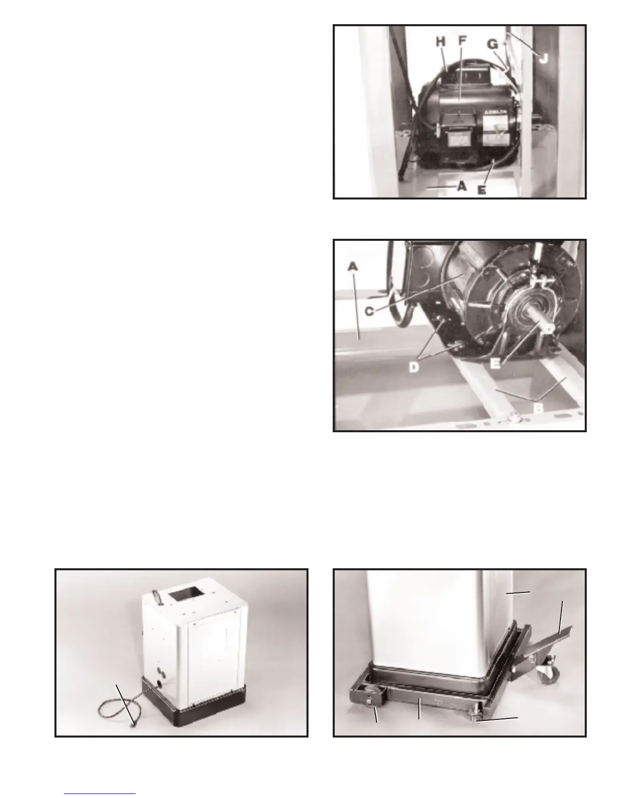
3. Remove two mounting screws, one of which is
shown at (E) Fig. 10, that are holding motor (F) to the top
of st and (A ). IMPORTANT:D O N OT REMOVE CABLE
TIE (G) T H AT IS HOLDING SWITCH CORD(H)TO VER-
TICAL MOUNTING BAR (J), UNLESS Y O U A R E USING
THE ACCESSORY 28-984 HEIGHT ATTACHMENT O N
THE BAND SAW .THIS CABLE TIE (G),WILL KEEP
THE SWITCH CORD (H) FROM CONTACTING THE
M O TO R PULLEY O R BELT DURING OPERATION.
Fig. 10
Fig. 1 1
Fig. 12
ASSEMBLING
MOTORTO STAND
1. To make the motor assembly easier, turn stand (A)
Fig. 1 1, on it s side with two horizont al bars (B) down as
shown.
2. Position motor (C) Fig. 1 1, on two horizont al support
bars (B) as shown, and fasten with four 3/4 long carriage
bolt s, two of which are shown at (D), and four flanged nut s.
IMPORTANT:M A K E CERTAIN M O TOR SHAFT (E) IS
O NTHE SAME SIDE OF THE STAND AS THELARGE
OPENING IN THE TO P O F T HE STA N D BEFORE TIGHT-
ENING CARRIAGE BOLTS (D). Further motor alignment
will be necessary af ter band saw is fastened to st and.
Fig. 13
3. Insert power cord plug (G) Fig. 12, through the bottom hole of the band saw st and to the out side of the st and.
4. Carefully turn the st and right side up.
IMPORTANT:Before assembling the band saw to the st and, we suggest that you place the st and (A) Fig. 13, onto
the mobile base (B), with the foot pedal lever (C) in the raised position as shown, so the wheels (D) and
rubber feet (E) are in full cont act with the floor surface.
A
C
E
D
B
G
 Loading...