15
Fig. 37
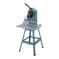
ALIGNING BORING BITS
(For 32-325 Line Boring Machine Only)
1. Place a flat piece of wood (A) Fig. 37, on the table
and against the fence as shown. Pull operating handle
downward until ANY ONE boring bit (B) first contacts the
top of the wood surface (A). NOTE: If all boring bits (B)
contact the top surface of the wood at the same time, no
alignment is necessary.
2. If any of the boring bits (B) Fig. 37, are not contacting
the wood surface (A), remove each bit that does not
contact the board one at a time. Loosen the set screw in
the shank end of the bit by the same amount that the bit
does not contact the wood. Reassemble the bit into the
same spindle as far as it will go, and tighten the spindle
set screw. After all bits have been adjusted, go back to
step 1 and recheck the alignment.
B
A
Fig. 38
ALIGNING BORING BITS
(For 32-326 Pneumatic Line Boring Machine
Only)
1. Cut a straight piece of wood (A) Fig. 38, two inches
high by sixteen inches long. Place the wood (A) on the
table directly underneath the 13 boring bits (B) as shown.
2. If any of the boring bits (B) Fig. 38, are not contacting
the wood surface (A), remove each bit that does not
contact the board one at a time. Loosen the set screw in
the shank end of the bit by the same amount that the bit
does not contact the wood. Reassemble the bit into the
same spindle as far as it will go, and tighten the spindle
set screw. After all bits have been adjusted, go back and
recheck the alignment.
B
A
Fig. 39
ASSEMBLING CLEAR
PLASTIC GUARD
1. Remove protective cover from guard.
2. Assemble the clear plastic guard (A) Fig. 39, to the
front of the boring head making sure the two slots (B)
are engaged with the two spacers and screws (C).
IMPORTANT: It will be necessary to bend the guard
(A) outward slightly at the center, as shown, when as-
sembling the guard.
C
B
C
B
A
Fig. 41
B
A
WRENCH STORAGE
A hole and rubber grommet (A) Fig. 41, is provided on the
top of the machine to store the wrench (B) supplied as
shown.
 Loading...